I have a center tapped transformer marked 400-0-400 Volts at 200mA.I prefer his hybrid power supply with tube rectifier and diodes. To cut down on cost, I would use an easier to find power transformer with one high voltage winding, 800VCT or 400V-CT-400V or similar, with a center tap you can use its half voltage for the driver stage or variation of that, like below. Regardless how you build it, it's going to be heavy with irons and costly. Good luck!

This means each leg (0-400V) is 100mA.
If, isolating the central wire, I measure the extremes will I have 800V: are these always at 200mA or is the usable current halved at 100mA?
revival56,
Great question!
The answer is complex, but here are the issues, and finally a chart you can find online.
The answer to 100mA versus 200mA is according to the manufacturer's specifications, including whether the specification is for Center Tapped full wave; Or End to End with a Bridge rectifier.
I bet the answer is 1/2 the current rating if you use the secondary end to end full wave bridge rectifier.
For a center tapped winding, if you use it that way, each 1/2 winding is only used on 50% of the alternations.
If you use the secondary end to end, both 1/2 and 1/2 windings are use 100% of the alternations.
The heating is according to the integral of I-squared of the winding(s).
And, the current rating is also different for:
A Resistor load (no rectifiers)
Rectifier(s) driving a Capacitor input filter (the lowest effective current rating, versus the transformer's temperature rise . . .
(heating of both the secondary, and the primary too).
The I squared integral is maximum for cap input filters, more heat.
And, you really need to make extremely short wiring to the input capacitor (lots of fast rise time current, lots of high frequency trash).
Rectifier(s) driving a Choke input filter
Hint:
Go to the Hammond transformer site.
They have a real good chart of various circuits loading the secondary.
1/2 wave, full wave, center tap, end to end winding, resistor load, capacitor input filter, choke input filter, etc.
A choke input filter maximum DCV is 0.9 x Vrms (less DCV than that, you have to include all the other voltage losses)
800Vrms = < 720VDC
A capacitor input filter maximum DCV is 1.414 x Vrms (less DCV than that, you have to include all the other voltage losses)
800Vrms = < 1,131 VDC
Watch out for what happens to a choke input filter power supply, before the output tube draws current,
the B+ will rise towards 1.414 x Vrms; 1,131 VDC
Filter caps need to be rated to at least 1500 VDC, and rectifiers need to have Peak Inverse Voltage ratings (PIV) of at least 3000V to have some margin if there is a power mains transient.
Some voltage drops, according to the load current:
Power transformer primary DCR, secondary DCR, Vacuum Tube Rectifier (or solid state small V drop), Series R that protects the tube rectifier if there is a cap input filter, Choke DCR (series R is not needed to protect the tube rectifier) , next Series R to the next cap, etc.
Mono-block 211 amplifiers is one thing. Stereo 211 amplifiers is another thing (contact your Hernia Surgeon).
Now you know why some people do not design a 211 amplifier, it is not only scary high voltages, it is brute force weight and part$.
Good luck, and have fun with the power supply design.
You will become an Artist and a Scientist.
Last edited:

6A3sUMMER :
As I do not have much knowledge of electronics, I only partly understood the arguments, which I promise to look into.
In order for me to better understand the crux of the matter, perhaps I should give a simpler example.
I have a 170-0-170 Volts 150mA transformer with 3 outgoing wires for connections.
I wish to have a secondary without CT: 0-340 Volts.
I think it is possible to leave the central wire (the zero) unused and draw 0V and 340V on the other 2 remaining wires at the ends.
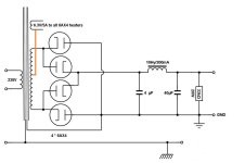
If it is technically right and possible so far, I would use this 0-340V secondary to make a power supply like the one in the picture below.
According to my calculations I should find about 410-430 Volts at the output.
What I need to know here is whether this output voltage is always available for a load of 150mA or half that (75mA).
Thank you for your detailed and very articulate reply.Good luck, and have fun with the power supply design.
You will become an Artist and a Scientist.
As I do not have much knowledge of electronics, I only partly understood the arguments, which I promise to look into.
In order for me to better understand the crux of the matter, perhaps I should give a simpler example.
I have a 170-0-170 Volts 150mA transformer with 3 outgoing wires for connections.
I wish to have a secondary without CT: 0-340 Volts.
I think it is possible to leave the central wire (the zero) unused and draw 0V and 340V on the other 2 remaining wires at the ends.
If it is technically right and possible so far, I would use this 0-340V secondary to make a power supply like the one in the picture below.
According to my calculations I should find about 410-430 Volts at the output.
What I need to know here is whether this output voltage is always available for a load of 150mA or half that (75mA).
Attachments
You should be able to source 150mA, but it is not advisable to use the full 150mA.
https://www.duncanamps.com/psud2/
https://www.duncanamps.com/psud2/
Power transformers are generally specified for DC output current for the classic/ancient application with two vacuum diodes and the center-tap to ground. A full wave bridge (like yours) gives twice that DC voltage, so would otherwise mean that only half of the DC current would be within rating. But the bridge is slightly more efficient, so you can cheat the 75mA DC rating up a bit. Not double, but some, if you absolutely must.I have a 170-0-170 Volts 150mA transformer with 3 outgoing wires for connections.
I wish to have a secondary without CT: 0-340 Volts.
I think it is possible to leave the central wire (the zero) unused and draw 0V and 340V on the other 2 remaining wires at the ends.
If it is technically right and possible so far, I would use this 0-340V secondary to make a power supply like the one in the picture below.
According to my calculations I should find about 410-430 Volts at the output.
What I need to know here is whether this output voltage is always available for a load of 150mA or half that (75mA).
In your post #23 circuit the diode heaters could also be referenced to the HV transformer's (otherwise unused) center tap. Slightly lower voltage stress.
All good fortune,
Chris
revival56,
The voltage will change with the load current.
All the resistances in the circuit, and the rectifier variable voltage drop versus current can not be avoided.
6AX4-GT max DC 137mA
6AX4-GTA and 6AX4GTB max DC 165mA
Example estimate:
Primary DCR 10 Ohms, translates onto the secondary at the turns ratio increase 10 x (340/230) = 15 Ohms
Secondary DCR 20 Ohms
Choke DCR 50 Ohms
We have:
15 Ohms + 20 Ohms + 50 Ohms = 85 Ohms
75mA and 85 Ohms = 6.4V
137mA and 85 Ohms = 11.6V
Rectifier x 2 in series; 32V x 2 @ 250mA = 64V; 250mA is the peak rectifier current into a capacitor input filter, the DC load current is far less than that.
The peak current of the rectifier into the 4uF cap: with DC load of 75mA, the peak rectifier current might be 200mA.
We might have 60V drop in 2 series rectifiers at 200ma peak rectifier current.
6.4V + 60V = 66.4V drop
If we have 137ma, we have a little more drop, perhaps 11.6V + 64V = 75.6V drop
These are approximations, your mileage may vary.
Thanks everyone for the replies.
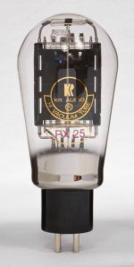
The design of this amplifier foresees a load of about 50-60mA for the power tube (PX25 KR Audio) + the load of the driver tube (E55L) which should not exceed 30-35mA.
So I need to have 85-95mA available and even something more so as not to overload the transformer.
To reduce the load towards the total 75mA of absorption I could make the PX25 work at 50mA and change the E555L driver with some tube capable of giving the right swing with 15mA and even less.
The PX25 KR works well at 360-380V/50-60mA and the grid negative should be between -20 and -40V (estimated around -30 on the tube bends). Therefore I think it is very easy to drive this tube and the choice of driver should therefore be very wide.
P.S. : I forgot one thing: of course there are 2 150mA 170-0-170 transformers to be used on 2 independent mono chassis.
Attachments
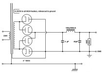
Do you mean to ground the dampers like this? :In your post #23 circuit the diode heaters could also be referenced to the HV transformer's (otherwise unused) center tap. Slightly lower voltage stress.
Attachments
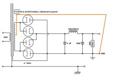
No, I meant to reference the diode heaters' (6.3VAC) winding to the HV secondary center-tap, instead of ground. Damper diodes are very forgiving of multi-KiloVolt positive voltages on their cathodes, but it's cost-free to bring the heaters up to half B+ .Do you mean to ground the dampers like this? :
This raises the question: What voltages appear at that center-tap? Imagine dividing the first (4uF) capacitor into two series'd 8uF caps. If the junction of those series'd caps were to be connected to the HV secondary center-tap, no current would flow in the connection (for an ideal, perfectly balanced case). That shows that the center-tap sits at half B+, and the dynamic cathode voltages are left as an exercise. Arf!
All good fortune,
Chris
In this way ?In your post #23 circuit the diode heaters could also be referenced to the HV transformer's (otherwise unused) center tap. Slightly lower voltage stress.
Attachments
Update:
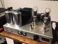
A friend of mine who is much more capable than me with high voltages and tube amp mechanics built the 211 Uesugi amp for me with my components.
We followed almost quite strictly the schematic, except with the addition of DC heating of the triodes, an additional switch for the plate voltage, an additional little circuit with vu-meters and plugs to adjust the bias current, a remote volume control and the possibility to switch between two sources, 2 x10uF 1500V caps in parallel after the HT supply coil (instead of 2x 20+20 in series), an extra 0,1FKP decoupling cap soldered directly on the HT connection of the output transformer for the microdynamics. The values of a pair of resistors also had to be somewhat adjusted to get the right operating points.
We made use of film foil capacitors (MKP etc) everywhere it was possible (IIRC the only exception is inevitably for the DC supplies of the 211 with 20,000uF or so).
The 211 are NOS RCAs from 1943. Resistors are Philips Pro 1 to 3 almost throughout, the liaison cap of 0,022 is a KP.
It's a fantastic, extremely dynamic amplifier. Comparable to my reference and preferred PP EL84 amp but with the sensation of additional headroom although the 211 delivers a little less power on paper. My friend had invited some people when running the first listening sessions, and comparisons where made with various tube amps, both PP and SET, including another 211 SET brought in for comparisons; it was night and day on most criteria, especially the huge dynamics / liveliness. Everyone was surprised by the results.
Following my listening of such amps on various occasions in different places I was strongly prejudiced beforehand about the ability of this project to reproduce well the lower and upper end, to be lively, and to cope with anything else but a full range 8" speaker (especially the complex load of a passive Xover'd 3-way system with 2x15" BR enclosures as in my system). All these prejudices have been swept away, to my positive surprise.
There is just a very light hum audible on my system in the absence of music signal - which seems to be linked to the tendency to vibrate of one of the toroids in the power supply. It would appear that the rating for the HT could have been higher as the voltage doubler already absorbs half of the 200mA mentioned in the schematic and the bias of the 211 already yields about 50 to 60mA just for each 211. So a 400mA capacity for the 400V would have been a better option, it would seem.
Attachments
Last edited:

Elac310,
Correct.
The amplifier that uses 211 output tubes is DHT outputs, but uses input tubes with cathodes, and driver tubes with cathodes . . .
is not an ALL DHT amplifier.
With all DHT input, DHT driver, and DHT output tubes . . .
Do rectifier tubes that with cathodes, change the ALL DHT status?
Correct.
The amplifier that uses 211 output tubes is DHT outputs, but uses input tubes with cathodes, and driver tubes with cathodes . . .
is not an ALL DHT amplifier.
With all DHT input, DHT driver, and DHT output tubes . . .
Do rectifier tubes that with cathodes, change the ALL DHT status?
Last edited:
Upgrade the filament supply of the 211's with Coleman's regulators. All fears, all noise and, more importantly, all intermodulation distortion due to standard filament supply will literally disappear.The damn’ thing with this hobby is the perpetual pursuit of chimaeras…
And it’s not a DHT actually. That’s a main change we did for fears of excessive noise.
A DHT amplifier is normally an amplifier with DHT power tubes. An ALL DHT's amplifier is an amplifier with such tubes in all stages.
Last edited:
- Home
- Amplifiers
- Tubes / Valves
- Uesugi 211 (vintage 1971)