Gonna check the UGS Muses thread again, there's been some updates ") . Also, I want to change the relay switching board and here is the reason.
. Also, I want to change the relay switching board and here is the reason.
BONUS
_______________________________________________________________________________________________________________________________________________________________
I know mechanical relays is very often used when switching inputs as an example. There does exist solid state devices which does that silently, so let's look at what is available to us.
The FET is a simple switch that have depletion mode or enhancement mode. The depletion mode FET is normally a conductive switch, even if the gate is not driven to a voltage away from its other terminals' voltages (nc). To stop it from conducting, its gate must be driven beyond the voltage on its source. Enhancement mode FETs are (no), normally open and the gate usually needs its gate driven by a control circuit for it to conduct, depending on circuit details.
A relay can also be conductive without being enabled by electrical control. For example, a relay control circuit can lose power, but the load current can still flow through the normally closed relay terminals (nc). Or relays can have a (no) construction. Or they can have a latching construction so they remain closed or open even if the control circuit is not powered up. Magnets and mechanical gripping circuits can retain the state of the relay even during a power loss to the control circuit, while the load power is still continuing to draw current and maintain a voltage.
An analog switch uses enhancement mode MOSFETs that are n-channel (NMOS) and p-channel (PMOS) so that a full voltage swing can be conducted. PMOS and NMOS form complementary switches (CMOS). The CMOS analog switch is more sophisticated than single FET switches which often drop a Vt threshold voltage in common circuit configurations. The CMOS switch does not drop a Vt. An FET switch usually drops a Vt voltage from the load so full rail to rail switching is not achieved with simple drive circuits.
I use the CD4016 and CD4051 analog switches for tiny currents. Relays carry the biggest currents. FETs are used when the control circuits are expertly designed. Analog switches have integrated control logic, like level shifters and digital enables so the design task is easier
Further, let's look at what IcOn use in their IcOn4 Pro unit which is the latest iteration.
"I tried everything to improve their timing, to eliminate the break-before-make nature of relays, to switch them overlapped, use different PCB wiring and more. I finally accepted that it's impossible to make a fully silent switched volume control with reed relays. These parts are too slow. Every on/off switch generates a 0.5-1ms glitch as a small signal discontinuity. Our brains are very sensitive to this kind of glitch and detect it as a small clicking noise. Most the time you won't hear it but it depends on the music programme.
"I can reduce the level of glitch with smaller steps but it won't fix their length due to the lazy mechanical action. These clicks are very faint but having spent literally hundred of hours trying to kill them completely, I became more and more sensitive to them. What else could I try? The answer was obvious. I needed faster switches.
"Enter solid-state relays, analog or Fet switches (CMOS most of the time). Their switching times are a few thousand times shorter than reed relays, about 100ns instead of 1ms. They have practically unlimited life and near zero power consumption. All of that was perfect. What about their Ron resistance, linearity, switchable signal range, bandwidth? Were they at all used in top audio products? Two years of R&D experiments, comparisons and blind listening tests finally identified the best analog switches from several thousand types for my purposes. Finally no more clicking."
"As it turned out, analogue switches are frequently used in today's audiophile products but most the time are simply hidden inside DAC chips, high-end volume controllers like the Muses 72320 Pass Labs are fond of, streamers, digital and even high-end preamps. Very few people realize their presence because they do no harm. They conduct/cut signal without measurable distortion or noise, not just audio but video up to 10-15V. They are good enough in the €20-30K Mark Levinson and Boulder volume controllers and the PS Audio BHK Signature. Why should anybody be suspicious of them in my icOn? What's more, I use newer chips with 1/10th the on-resistance of the chips in previous preamps. In short, my Fet switches are the very best solution for any kind of stepped attenuator realized with resistors, transformers or autoformers. Which begs your question. Why offer reed relays or Fets? Though it's a bit strange to me yet a fact of life, there are many faith-driven audio customers. If they believe that reed relays are superior, they are. The customer is king.
* * *
Okay, we got some information there which is great. What we have so far is that IcOn is offering reed switches or Vishay CMOS analog switches. I will add these to the debate later so no need to check the source right away. So, we have FET's, CMOS, SSR (solid state relay) and we have the mechanical variant which is our traditional mechanical relay and our reed relay/switch.
While doing my research, I stumbled upon this and I quote.
Douglas Self wrote some interesting stuff about this topic in his books "Self on Audio"and "Small Signal Audio Design". Not only distortion is a problem with multiplexers. Control voltage feedthrough is much more ugly and needs a lot of effort to keep it out of your audiopath. In a conversation with a console designer he told me that the usual 4053 multiplexer is not even good enough for audio. There was a Philips version of the 4053 which had less CV feedthrough which he was using in his designs. Same chip from other manufacturers didn´t meet his specs - Jensenmann.
So basically, Douglas Self is saying that solid state is a bad idea as an audio signal switch. So let's keep that in mind, or just me, for when we get to comparisons of different devices. - which sort of brings us to the next part: Mechanical relay's, the std one. I wanted to find out which one was or is considered to be really good, so let's dive in. I am using diya here for convenience.
Comments from different people.

Alright, I think we are ready to pull up some spec and compare the units talked about + some of the ones I found. Before we do that, lets list the ones mentioned so far.
Comparison values.
Model Contact resistance (on state) - Contact speed - Contact capacitance (on state) - price/pcs
TI CD4016 - 5 to 15Ω - 15-100 nS - 4 pF - €0.45
TI CD4051 - 125 to 470Ω - 100's of nS - 30pF - €0.45
Vishay DG212 - 100 Ω - 200 to 300 nS - 16 pF €1.50
Vishay DG417 - 45Ω - 100s on nS - 30pF - €1
That was our CMOS or SSR variant. Next is the Panasonic and Omron mechanical relay.
Panasonic TQ - 50mΩ - 1-2 ms - Doesn't state, expect several pF - €3
Panasonic AGN - / - 4 ms - Doesn't state, expect several pF - €3-4
Omron G6K - 100mΩ - 3 ms - Doesn't state, expect several pF - €3
Omron G6B - 30mΩ - 10 ms - Doesn't state, expect several pF - €5
Teledyne 712 - 150mΩ - 4 ms - 0.4 pF €55 to 75
That was our traditional mechanical relays, and we can see the appeal in lower on-resistance compared to CMOS and SSR. The Teledyne 712 is a clear improvement over the CMOS and also the Panasonic & Omron traditional relays and a serious improvement in the capacitance region. The CMOS is faster but the other very important specs are much much worse. Let's move on to the reed relays.
Hamlin H3300 (dry) - 150 mΩ - 1-3 ms - Doesn't state, expect several pF
Hamlin H3600 (dry) - 150 mΩ - 1-3 ms - Doesn't state, expect several pF
Hamlin H700 (dry) - 150 mΩ - 1-3 ms - Doesn't state, expect several pF
Pickering 101 (dry) - 120-150 mΩ - 1 ms - 2.5 pF
Pickering 101 (wet) - 75-100 mΩ - 1ms - 4.5 pF
Pickering 112 (dry) - 120 mΩ - 0.5 ms - 1.5 pF
Pickering 103 (dry) - 120-150 mΩ - 0.5 ms - 0.1 to 0.45 pF
Pickering 200 (dry) smd - 120-200 mΩ - 0.5 ms - 2.5 pF €5
Pickering 200 (wet) smd - 75-100 mΩ - 2 ms - 4 pF €8
Coto 8L (dry) - 150 mΩ - 0.5 ms - 0.5 pF €2-6
Conclusion.
While the Teledyne 712 impresses when it comes to resistance and capacitance, the price does not. That is one expensive motherfucker and is actually not better than the Coto 8L. Coto does not offer mercury wetted, only Pickering as far as I can tell. While both Panasonic and Omron offers very good as in low on-resistance, they are relatively slow switching speed, they are mechanical relays after all, just like the reed switches. When it comes to the capacitance of Panasonic and Omron, it is not stated, another brand had 3-4 pF as their number, so I believe the capacitance is close to that. Pickering 103 has even better capacitance numbers than Coto 8L. And Pickering 200 is offered as both dry and wet and is also smd.
Sources.
1. FET vs. Analog Switch IC vs. Relay.
2. 6moon review of IcOn4 Pro.
3. Douglas Self comment.
4. DIYA relay's.
5. Mercury wetted.
6. NAIM 552.
7. Hamlin Reed Relay.
8. Reed relay sound - (nothing or very small)
__________________________________________________________________________________________________________________________________________________________________
Since the "music" actually goes through the relay, why not give the preamp the best one
. Also, I want to change the relay switching board and here is the reason.BONUS
_______________________________________________________________________________________________________________________________________________________________
I know mechanical relays is very often used when switching inputs as an example. There does exist solid state devices which does that silently, so let's look at what is available to us.
The FET is a simple switch that have depletion mode or enhancement mode. The depletion mode FET is normally a conductive switch, even if the gate is not driven to a voltage away from its other terminals' voltages (nc). To stop it from conducting, its gate must be driven beyond the voltage on its source. Enhancement mode FETs are (no), normally open and the gate usually needs its gate driven by a control circuit for it to conduct, depending on circuit details.
A relay can also be conductive without being enabled by electrical control. For example, a relay control circuit can lose power, but the load current can still flow through the normally closed relay terminals (nc). Or relays can have a (no) construction. Or they can have a latching construction so they remain closed or open even if the control circuit is not powered up. Magnets and mechanical gripping circuits can retain the state of the relay even during a power loss to the control circuit, while the load power is still continuing to draw current and maintain a voltage.
An analog switch uses enhancement mode MOSFETs that are n-channel (NMOS) and p-channel (PMOS) so that a full voltage swing can be conducted. PMOS and NMOS form complementary switches (CMOS). The CMOS analog switch is more sophisticated than single FET switches which often drop a Vt threshold voltage in common circuit configurations. The CMOS switch does not drop a Vt. An FET switch usually drops a Vt voltage from the load so full rail to rail switching is not achieved with simple drive circuits.
I use the CD4016 and CD4051 analog switches for tiny currents. Relays carry the biggest currents. FETs are used when the control circuits are expertly designed. Analog switches have integrated control logic, like level shifters and digital enables so the design task is easier
Further, let's look at what IcOn use in their IcOn4 Pro unit which is the latest iteration.
"I tried everything to improve their timing, to eliminate the break-before-make nature of relays, to switch them overlapped, use different PCB wiring and more. I finally accepted that it's impossible to make a fully silent switched volume control with reed relays. These parts are too slow. Every on/off switch generates a 0.5-1ms glitch as a small signal discontinuity. Our brains are very sensitive to this kind of glitch and detect it as a small clicking noise. Most the time you won't hear it but it depends on the music programme.
"I can reduce the level of glitch with smaller steps but it won't fix their length due to the lazy mechanical action. These clicks are very faint but having spent literally hundred of hours trying to kill them completely, I became more and more sensitive to them. What else could I try? The answer was obvious. I needed faster switches.
"Enter solid-state relays, analog or Fet switches (CMOS most of the time). Their switching times are a few thousand times shorter than reed relays, about 100ns instead of 1ms. They have practically unlimited life and near zero power consumption. All of that was perfect. What about their Ron resistance, linearity, switchable signal range, bandwidth? Were they at all used in top audio products? Two years of R&D experiments, comparisons and blind listening tests finally identified the best analog switches from several thousand types for my purposes. Finally no more clicking."
"As it turned out, analogue switches are frequently used in today's audiophile products but most the time are simply hidden inside DAC chips, high-end volume controllers like the Muses 72320 Pass Labs are fond of, streamers, digital and even high-end preamps. Very few people realize their presence because they do no harm. They conduct/cut signal without measurable distortion or noise, not just audio but video up to 10-15V. They are good enough in the €20-30K Mark Levinson and Boulder volume controllers and the PS Audio BHK Signature. Why should anybody be suspicious of them in my icOn? What's more, I use newer chips with 1/10th the on-resistance of the chips in previous preamps. In short, my Fet switches are the very best solution for any kind of stepped attenuator realized with resistors, transformers or autoformers. Which begs your question. Why offer reed relays or Fets? Though it's a bit strange to me yet a fact of life, there are many faith-driven audio customers. If they believe that reed relays are superior, they are. The customer is king.
* * *
Okay, we got some information there which is great. What we have so far is that IcOn is offering reed switches or Vishay CMOS analog switches. I will add these to the debate later so no need to check the source right away. So, we have FET's, CMOS, SSR (solid state relay) and we have the mechanical variant which is our traditional mechanical relay and our reed relay/switch.
While doing my research, I stumbled upon this and I quote.
Douglas Self wrote some interesting stuff about this topic in his books "Self on Audio"and "Small Signal Audio Design". Not only distortion is a problem with multiplexers. Control voltage feedthrough is much more ugly and needs a lot of effort to keep it out of your audiopath. In a conversation with a console designer he told me that the usual 4053 multiplexer is not even good enough for audio. There was a Philips version of the 4053 which had less CV feedthrough which he was using in his designs. Same chip from other manufacturers didn´t meet his specs - Jensenmann.
So basically, Douglas Self is saying that solid state is a bad idea as an audio signal switch. So let's keep that in mind, or just me, for when we get to comparisons of different devices.
- which sort of brings us to the next part: Mechanical relay's, the std one. I wanted to find out which one was or is considered to be really good, so let's dive in. I am using diya here for convenience.Comments from different people.
- The AGN is Panasonic's version of the Omron G6K, which is actually smaller (height). G6K uses Gold clad Silver terminals.
- Have a look at the relays used for semiconductor testing, also known as an RF relay, e.g. Teledyne 712 series.
- A decade ago there was a listening test in Klang&Ton, as far as I remember they favored the mercury wetted stuff.
- A mercury wetted relay has something like 30mR contact resistance.
- I think you will find that telecom relays are pretty good with these things. They are designed to switch rapidly over a long life time, unlike power relays which are can carry more current but don't switch as often. Just don't switch DC and your contacts will last a very long time - BrianDonegan – Twisted Pear Audio.
- > Well, if it has not to be an hard to get, exotic part, the industry quality Omron G6B has the same 30mR max contact resistance, Ag-alloy contacts, fully sealed. Costs however about the same as your mercury wetted relays.
- Why is mercury wetted relay used for low level high impedance circuits including many precision instruments ?
Take a look at your Omron G6 datasheet. It specifies a minimum current. Below that current, the contact resistance is undefined, because the relay actually need current to burn away the oxide layout at the contact to create micro-welding before you ever get your 30mR resistance (when new). Different from a liquid metal contact, all dry contact ages, and the contact resistance goes up during lifetime. - The Teledyne 712 is really nice. Yes, pricey, but well sealed, fairly fast, good contact metallurgy, and reasonably low power. The signal conduction portion of the armature is non-magnetic, and the whole package is small. If you need just a few really good relays and you can afford $25 for a DPDT, it's a good choice.
- The main reason for the development of the ruthenium sputtered contact types is the fact that the Hg ones are environmentally bad news, both in production as well as after discarding. I have used many years Pickering type 101 ruthenium types for audio switching without any apparent problems - Jan Didden
- Ok, these ones are not sensitive to mounting position, I guess that there is only a minuscule amount of mercury on contact surfaces, not the entire pool like some other types. Mercury content of these is sooo small compared to all those fluorescent lamps everywhere that I am not going to lose my sleep over that. Dunno, maybe these are not so good then as these have so little mercury.
- Quote from: "Freq Band": Is there anything "special" about these for handling audio signals ?
Mercury wetted rellays = very low noise.
It is metalurgic contact. It behaves like soldering. Nothing is better (... and nothing is harder to find). Very long ago mercury relays was rather common. Before the invention of the reed relay, mercury ones were the only way to get a small and good relay. Robert Hermeyer in Berlin was producer of mercury relays in 1950-ies. That relay performed like a thermometer. If some current was fed into the control branch, gas inside expands and moves mercury in the capilar. Mercury then connects two platinum wires inside capilar. Today, we use MOSFETS instead that relays, but for special purposes mercury relays could have better dynamic range - xvlk.
- I designed in Hg-wetted reeds, switching low-Z bulk metal foil Vishay resistors, for the Harman R&D group's fancy computer-controlled attenuator, although we never finished the project as they were having some budget problems. The design achieved about a 144 dB signal-to-noise ratio, so that I could say we were doing a real 24 bits.The relay on resistance is a little higher than direct clean gold or palladium reeds etc. sometimes, but as xvlk says it's like soldering and represents a new metallurgical junction each time you make. They are usually position-sensitive although there were some "mercury-film" ones that were not.Another advantage of Hg-wetted: essentially no contact bounce on make-break. People have used them as fast rise time pulse generators (with of course huge jitter and very slow repetition rates).For switching high power there are big clunky things called mercury displacement relays, where a plunger is pulled down into a mercury bath to push the mercury up to make contact with the electrodes. Magnecraft makes them, and the big ones have about a milliohm of resistance and switch a hundred amps. They are used for "mission-critical" applications and for situations where there could be explosive atmospheres. But they have the same "dry" contact behavior as a mercury reed. When the original Harman design was going to switch speakers and amplifiers, I specified these (or maybe the somewhat smaller ones) for that portion of the switching, and was considering showing how good the switch was by running an MC cartridge signal through them and noting the lack of degradation - Bcarson.
- The NAIM 552 is close to twice as expensive as a BT, with twice as much hardwire, and a whole lot more Reed switches (CP Clare types, the later Sumida RemTech Corp. PRMA, now Coto 8L). Yet nobody seems to get upset about the 552, notta bad for a preamp that uses a couple of motorized Alps pots for volume attenuation. Jolly old Britain, thank goodness the Naim Powerline is only a mere $600.
- Texas Instruments CD4016 & CD4051 CMOS analog switch/multiplexer.
- Vishay DG212 CMOS analog switch, lets also throw in the DG417 here. (IcOn)
- Panasonic TQ-2 and AGN relays.
- Omron G6K and G6B.
- Teledyne 712.
- Hamlin Reed Relay series. (IcOn)
- Pickering 101 series - reed switch.
- Pickering 112-1-A-5/2
- Additional Pickering reed switches.
- Coto 8L series.
Comparison values.
Model Contact resistance (on state) - Contact speed - Contact capacitance (on state) - price/pcs
TI CD4016 - 5 to 15Ω - 15-100 nS - 4 pF - €0.45
TI CD4051 - 125 to 470Ω - 100's of nS - 30pF - €0.45
Vishay DG212 - 100 Ω - 200 to 300 nS - 16 pF €1.50
Vishay DG417 - 45Ω - 100s on nS - 30pF - €1
That was our CMOS or SSR variant. Next is the Panasonic and Omron mechanical relay.
Panasonic TQ - 50mΩ - 1-2 ms - Doesn't state, expect several pF - €3
Panasonic AGN - / - 4 ms - Doesn't state, expect several pF - €3-4
Omron G6K - 100mΩ - 3 ms - Doesn't state, expect several pF - €3
Omron G6B - 30mΩ - 10 ms - Doesn't state, expect several pF - €5
Teledyne 712 - 150mΩ - 4 ms - 0.4 pF €55 to 75
That was our traditional mechanical relays, and we can see the appeal in lower on-resistance compared to CMOS and SSR. The Teledyne 712 is a clear improvement over the CMOS and also the Panasonic & Omron traditional relays and a serious improvement in the capacitance region. The CMOS is faster but the other very important specs are much much worse. Let's move on to the reed relays.
Hamlin H3300 (dry) - 150 mΩ - 1-3 ms - Doesn't state, expect several pF
Hamlin H3600 (dry) - 150 mΩ - 1-3 ms - Doesn't state, expect several pF
Hamlin H700 (dry) - 150 mΩ - 1-3 ms - Doesn't state, expect several pF
Pickering 101 (dry) - 120-150 mΩ - 1 ms - 2.5 pF
Pickering 101 (wet) - 75-100 mΩ - 1ms - 4.5 pF
Pickering 112 (dry) - 120 mΩ - 0.5 ms - 1.5 pF
Pickering 103 (dry) - 120-150 mΩ - 0.5 ms - 0.1 to 0.45 pF
Pickering 200 (dry) smd - 120-200 mΩ - 0.5 ms - 2.5 pF €5
Pickering 200 (wet) smd - 75-100 mΩ - 2 ms - 4 pF €8
Coto 8L (dry) - 150 mΩ - 0.5 ms - 0.5 pF €2-6
Conclusion.
While the Teledyne 712 impresses when it comes to resistance and capacitance, the price does not. That is one expensive motherfucker and is actually not better than the Coto 8L. Coto does not offer mercury wetted, only Pickering as far as I can tell. While both Panasonic and Omron offers very good as in low on-resistance, they are relatively slow switching speed, they are mechanical relays after all, just like the reed switches. When it comes to the capacitance of Panasonic and Omron, it is not stated, another brand had 3-4 pF as their number, so I believe the capacitance is close to that. Pickering 103 has even better capacitance numbers than Coto 8L. And Pickering 200 is offered as both dry and wet and is also smd.
Sources.
1. FET vs. Analog Switch IC vs. Relay.
2. 6moon review of IcOn4 Pro.
3. Douglas Self comment.
4. DIYA relay's.
5. Mercury wetted.
6. NAIM 552.
7. Hamlin Reed Relay.
8. Reed relay sound - (nothing or very small)
__________________________________________________________________________________________________________________________________________________________________
Since the "music" actually goes through the relay, why not give the preamp the best one
Last edited:
I used it only at low levels to feed my js, I guess 1vrms max(both the ugs and the autotransformer).
Like I was saying earlier my ears like the sound and I like the entire concept and there is no obvious coloration on the sound.
Each gain stage if properly implemented has the thd so low that you can call it character and not thd, at least this is how I see it.
I think that with good cores you can get good performance.
The core you want to use seems to have a small cross section effective area but being so cheap with 50€ you can buy 1kg of 0.25mm enameled wire and also 2 cores to try the concept. If you like it you can go ahead further experimenting with other core geometry or even material(there is finemet also).
My advice is to stop reading so much and start building more. You gathered some nice info about components that could serve you well.
The UGS Muses is a fine preamplifier and I have access to the fine PASS gain stage, so I should definitely go all in on it, make my mark, and fully build one and use this preamplifier as my reference. No matter, one always need a reference for when new stuff is pitted against.
Its been a long journey that is for sure. Find or discover what one want or need. These things take time.
Its been a long journey that is for sure. Find or discover what one want or need. These things take time.
Most important is to build something in the end.
Most of the time I am like you, I decide on something to build and then because I go ahead and read too much(because I want the cherry on the cake) I take another route and most of the time I end up with doing nothing and in the meantime the years pass by.
Lately I started to take another approach and finally managed to draw some pcbs, build a few circuits and most important I made an idea of the sound I get and how much I like it.
There are a lot of geat ideas and circuits on the Pass forum, many of them designs from Nelson and ZM.
If it was that these circuits would have been in comercial products they would cost thousands or maybe more. Having the info right under our nose the interest starts to get lower and we want unobtainable things because the human is like that.
You can start by building your ugs pre, you will have a good preamp and also a nice test bed for other gain stages. You just remove the ugs pcbs and connect whatever you wish. To me this seems unlimited fun and lately I started to enjoy it more.
I heard a quote some time ago and it goes as follow:
Indeed, Pass and ZM have contributed immensely and we should be grateful... which I am. And I am immensely lucky for I have, at the tip of my finger, access to some of the finest schematics and solutions and the UGS MUSES is among that. The one thing I want to do now that I have a much greater understanding of how to design a PCB, or what is part of good PCB design, is to reorganise the UGS MUSES such that the individual circuits ends up on the same board with proper ground flooding and the utilization of mainly SMT components as well as a few other neat upgrades.
Immediately and in the same spirit as the preamp, do similar work on the intended power amplifier, which also is top shelf, fine wine, equipment... not a PASS amplifier, but I am sure its in the spirit of PASS since its biased hot. The first 20 watts are in class A, and class AB between 20-220W (8 ohm). This amplifier was invented almost 2 decades before PASS introduced a similar approach (XA25) and was updated over the years. The main reason that I fell in love with this amplifier is the utilization of only 2 power FETs, one per voltage polarity. It can't get any simpler than this and the smoothness of this amplifier is much down to this architect. The lowest amount of crossover noise.
I need to free my mind from worries over "is this good enough" such that I can start working on my loudspeakers. I want to develop my own ribbon tweeter and open baffle loudspeaker, that is what I want.
Yes yes, I will post pictures of the preamp when it is done... Don't hold your breath, but it will come
In the light of your comment and "our" hunt for ever better performance, its very easy to get caught in a loop of rinse and repeat, while we forget why we are here.. or something to that effectAudiophiles don't listen to music, they listen to their equipment.
Indeed, Pass and ZM have contributed immensely and we should be grateful... which I am. And I am immensely lucky for I have, at the tip of my finger, access to some of the finest schematics and solutions and the UGS MUSES is among that. The one thing I want to do now that I have a much greater understanding of how to design a PCB, or what is part of good PCB design, is to reorganise the UGS MUSES such that the individual circuits ends up on the same board with proper ground flooding and the utilization of mainly SMT components as well as a few other neat upgrades.
Immediately and in the same spirit as the preamp, do similar work on the intended power amplifier, which also is top shelf, fine wine, equipment... not a PASS amplifier, but I am sure its in the spirit of PASS since its biased hot. The first 20 watts are in class A, and class AB between 20-220W (8 ohm). This amplifier was invented almost 2 decades before PASS introduced a similar approach (XA25) and was updated over the years. The main reason that I fell in love with this amplifier is the utilization of only 2 power FETs, one per voltage polarity. It can't get any simpler than this and the smoothness of this amplifier is much down to this architect. The lowest amount of crossover noise.
I need to free my mind from worries over "is this good enough" such that I can start working on my loudspeakers. I want to develop my own ribbon tweeter and open baffle loudspeaker, that is what I want.
Yes yes, I will post pictures of the preamp when it is done... Don't hold your breath, but it will come
I don’t think it’s worth redesigning the muse preamp main pcbs, they are very good as they are(to mention that many users built the preamp and had no noise issues, now why would you want to redesign something that is working good I don’t know), my guess is that it’s just your brain that lately was trained to improve everything it sees and it takes you that way making you lose time with improvements that most of the time are not needed. This way you end up only with ideas instead of working projects.
So take out everything from the drawers that belongs to the ugs muse pre, make a list with what you have, see what you miss and order the pieces. In a few days you will have something working on your table that will make you so proud of you that you will regret you waited so long and didn’t start earlier.
So take out everything from the drawers that belongs to the ugs muse pre, make a list with what you have, see what you miss and order the pieces. In a few days you will have something working on your table that will make you so proud of you that you will regret you waited so long and didn’t start earlier.
Redesigning is maybe a bit misleading since it sounds like I will ATTACK the schematic and remove / add stuff. That is not the case . Its only a matter of optimization and improvement in the component communication and grounding scheme. Plus, I really don't like green solder mask. The colour have nothing to do with function but all to do with being visually pleased. Some can live with their projects in a shoebox, wooden crate or even a biscuit tin box... I need a bit more . I want both my eyes, ears and OCD to be satisfied and unless I got to fiddle with the design and layout, I will not be fully satisfied.
Gonna give you an example: The ground is part of the signal path, the active signal passes via the ground, the negative portion of the signal. Then look at a PCB, we know that its conductive portion is the copper sheet and the use of copper is a necessity. But we could use aluminium or even silver, the later would be very expensive, but technically, we could use silver to improve the performance. So why then, if copper is the minimum quality metal for our PCB's, do we end up with aluminium or sometimes, iron, in our chassis, as part of the ground-negative signal path ... Wouldn't using copper as part of the chassis ground be a logical move ?
If I told you that aluminium or iron speaker cables is as good as copper, you would perhaps call me an idiot, but I am not an idiot, so I am not making that claim
Back to the chassis. Earth, ground and negative, are sometimes... well, often, treated as the same and I'm uncomfortable with it. The chassis should be part of the shield and the negative portion of the signal should be part of the ground, isolated from one another and in order to get proper shielding, you need professional connectors which earths the varies chassis and signal cables BEFORE the active signal such that outside **** is removed. This is easier to do than what one initially might think.
. Its only a matter of optimization and improvement in the component communication and grounding scheme. Plus, I really don't like green solder mask. The colour have nothing to do with function but all to do with being visually pleased. Some can live with their projects in a shoebox, wooden crate or even a biscuit tin box... I need a bit more . I want both my eyes, ears and OCD to be satisfied and unless I got to fiddle with the design and layout, I will not be fully satisfied.Gonna give you an example: The ground is part of the signal path, the active signal passes via the ground, the negative portion of the signal. Then look at a PCB, we know that its conductive portion is the copper sheet and the use of copper is a necessity. But we could use aluminium or even silver, the later would be very expensive, but technically, we could use silver to improve the performance. So why then, if copper is the minimum quality metal for our PCB's, do we end up with aluminium or sometimes, iron, in our chassis, as part of the ground-negative signal path ... Wouldn't using copper as part of the chassis ground be a logical move ?
If I told you that aluminium or iron speaker cables is as good as copper, you would perhaps call me an idiot, but I am not an idiot, so I am not making that claim
Back to the chassis. Earth, ground and negative, are sometimes... well, often, treated as the same and I'm uncomfortable with it. The chassis should be part of the shield and the negative portion of the signal should be part of the ground, isolated from one another and in order to get proper shielding, you need professional connectors which earths the varies chassis and signal cables BEFORE the active signal such that outside **** is removed. This is easier to do than what one initially might think.
Threat the chassis and wire shield as "one component" together with a separate earth cable on the chassis which creates your Faraday cage via BNC connectors which connects the shield before the signal, in stark contrast to the junk RCA which connects the signal before the shield, keeping an open path for EM and static electricity to enter before it makes the shield connection - that is the hum, clicks and pops you hear when you connect a cable. Sometimes enough to fry components. And while one could argue with: "Then don't disconnect or connect the cables when the equipment is live", you are still keeping the chance to critical failure open if you happen to forget to follow "the rule". It is far better to, in the design stage, remove the issue.
The 1930's called, they want their connector back ...
While the treatment or how I related to, above, is a bit more work and cost, its nothing that have to be earth shattering compared to the chassis ground RCA connectors approach. The copper ground is basically nothing more than a thin copper sheet with some holes in it and can be made/done relatively cheap.
I think my point is, to a degree. Before making absolute advices and "you don't need that's", one should be very confident in .. "you don't need that", and in my humble opinion, this knowledge is dynamic, like science. "What was might not be anymore". If the shoe box works as your electronics box and there is no EMF interference in the spot you placed it, why bother... right ?
Why oh why do we do the things we do... the answer is because we want to or we like doing it that way. Sometimes it is out of necessity or for safety, point being: There is always improvements to be had, that is not the issue, the issue is when do you like to stop ? ... Why are N. Pass still designing amplifiers, does the ones he have suck ? ... no, the answer to why is: Because he can... and want to. In his mind, each amp is a stepping stone to something different, better, perhaps even, closer to the ideal amplifier, which is, if we remember, a wire with gain...
Anyway, before I go to far out on my tangent. One mans best idea is another's worst and that is the reason we are here, why we are all here. Because maybe, just maybe, we are a teeny tiny worried that we are the "another's worst" and we just want make sure this is not the case
It's been a while hasn't it.. and not a God damned thing to show, makes one wonder sometimes, what the hell am I doing.
Well, I am learning and discovering, and while one could build at the same time, what happens when one get stuck in the land of theory, discovering I don't know the fundamentals. Then it gets scary. I can't just throw out thousands of kroner or euro, cross my heart and hope to die, that its a good investment.. and yes, I know, most people usually are on their way with the project before they start a thread... waste of time, blah blah.. I know. But my intention was good...
As a matter of fact, I have the UGS Muses boards in front of me, just as friendly support for my work on the optimized and fully integrated one. I especially want the gain stage (yes THAT stage) to be incorporated directly on the motherboard. And beyond that, looking at the power amp which also will get an 2022 update.
It has been frustrating from time to time, not enough money, not enough knowledge and projects evolving... but I am back to where I started (almost), back to the UGS Muses. NOT as planned, meaning from scratch, but with some updated to the original one. I am, to be honest, tired or running around looking for "better", so I am going to pour my heart into the UGS MUSES Scion and intended power amp, and update when I actually have something real.
No more excuses, lets just leave it at that..
.....This amplifier was invented almost 2 decades before PASS introduced a similar approach (XA25) and was updated over the years. .......
which one is that, exactly?
so I can search and maybe learn trick or two ......
Well, that's just I what I thought........It's been a while hasn't it.. and not a God damned thing to show, makes one wonder sometimes, what the hell am I doing.
Well, I am learning and discovering, and while one could build at the same time, what happens when one get stuck in the land of theory, discovering I don't know the fundamentals. Then it gets scary. I can't just throw out thousands of kroner or euro, cross my heart and hope to die, that its a good investment.. and yes, I know, most people usually are on their way with the project before they start a thread... waste of time, blah blah.. I know. But my intention was good...
As a matter of fact, I have the UGS Muses boards in front of me, just as friendly support for my work on the optimized and fully integrated one. I especially want the gain stage (yes THAT stage) to be incorporated directly on the motherboard. And beyond that, looking at the power amp which also will get an 2022 update.
It has been frustrating from time to time, not enough money, not enough knowledge and projects evolving... but I am back to where I started (almost), back to the UGS Muses. NOT as planned, meaning from scratch, but with some updated to the original one. I am, to be honest, tired or running around looking for "better", so I am going to pour my heart into the UGS MUSES Scion and intended power amp, and update when I actually have something real.
No more excuses, lets just leave it at that..

J.R
Hi
In the meantime, I have just built this new pre-amp. ( While you are just searching and searching for the "ultimate solution")


It is fully balanced from input to output. Muses volume chips. Gain stage (5.9dB gain) with OPA 1656. It also have a remote control.
Measurments: Those are done by a Diy friend of mine with a Rohde &Schwarz UPV.
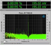
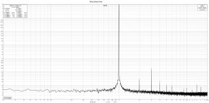
FFT gain 1V and 1 khz:

THD+N curve:
THD+N vs. voltage out .Signal in goes from 30mV to 400mV.
Volume control set at 0dB 5,9db gain)

Remarks from my Diy friend:
This is good stuff. Below 1V, noise dominates the curve. Between 1V and 3V, THD+N is 0.0004%, which is the lowest I can measure. Above 3V, some harmonic distortion starts to take effect, and it goes up to 0.003% at 8V. 8V is far above what a preamp should normally deliver, but it's nice to see that it also manages that without destroying the signal.
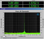
To see exactly how the distortion looks at 8V on the curve above, we took a measurement of this:

We see that there is something of the third order that accounts for this increase.
At slightly more normal levels, a preamp never delivers more than 2V at the output, and then it looks like this: (input is 1V)

The measuring instrument itself is unable to measure better than 0.0003% and it has a second-order measurement error of -124dB.
We see that the preamplifier almost manages to match the measuring instrument. The higher harmonics are below -130dB and so low that it is almost certainly inaudible. To put it in perspective, I can remind you that the maximum signal/noise on a CD is 96 dB. This is exactly 50 times better.
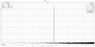
It may be interesting to check what happens to signals when the volume control attenuates the signal. By turning down 20dB, we get this result: (singal input is 1V)
Volume control at -20dB

When the volume is muted, parts of circuits and wires have a higher impedance to ground and the system becomes more sensitive to radiated noise. We also see that we get a slight upsurge of network-related noise at 150Hz, 250Hz, and 450Hz. One would have liked to see that these were not there, but since these are more than 110dB lower than the (already low) signal of 195mV, it has no effect. The voltage on these "posts" is 0.0000006V (0.6uV). It is so small that it is completely unproblematic.
To put it into perspective:
Even if this noise is amplified 22 times, which is common for a power amplifier, it will only be 13uV. That corresponds to a power of 0.000000000021W (21picoWatt).
If you have speakers with 100dB sensitivity, this will create a sound pressure of -7dB SPL 1 meter away from the speaker. It goes without saying that this is inaudible.
Noise:
These measurements were taken with the inputs shorted.
Noice floor. Volume at 0dB

Here, the noise floor is measured with a volume control of 0dB (full volume). It is an A-weighted measurement. 3.2uV total overall noise from 20Hz to 20kHz is very low. Again, it almost matches the instrument which can measure down to 1uV.
With a volume control of -16dB, the noise increases slightly up to 4.8uV. We recognize the bars from the previous measurement that appear on one channel. This time the measurement is in dBV and we see that they are at -134dBV. It corresponds to 0.2uV and, as mentioned, is far below the audible level.

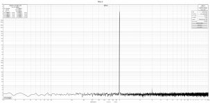
IMD
This is a difficult test where two signals (both at 2V) must be reproduced at the same time, but here too the preamp shines with very good measurements. It is over 107dB from the signals down to the first side bands. Otherwise, it's nothing. Only what should be there.
BW=80Khz. 19K and 20K@1000mV. Volume at 0dB.

All the remarks from my diy friend who measured this pre-amp is italics
Summary
Obviously, these are fantastic readings in my book and a good improvement from the last time Johnny was here.
Yes, we can measure both one and the other far down there in the depths, but it is not far off that the preamp measures as well as the measuring instrument. For all practical purposes, this preamp will be completely free of both noise and distortion at all volume settings.
Good work
Regards
J.R
In the meantime, I have just built this new pre-amp. ( While you are just searching and searching for the "ultimate solution")
It is fully balanced from input to output. Muses volume chips. Gain stage (5.9dB gain) with OPA 1656. It also have a remote control.
Measurments: Those are done by a Diy friend of mine with a Rohde &Schwarz UPV.
FFT gain 1V and 1 khz:
THD+N curve:
THD+N vs. voltage out .Signal in goes from 30mV to 400mV.
Volume control set at 0dB 5,9db gain)
Remarks from my Diy friend:
This is good stuff. Below 1V, noise dominates the curve. Between 1V and 3V, THD+N is 0.0004%, which is the lowest I can measure. Above 3V, some harmonic distortion starts to take effect, and it goes up to 0.003% at 8V. 8V is far above what a preamp should normally deliver, but it's nice to see that it also manages that without destroying the signal.
To see exactly how the distortion looks at 8V on the curve above, we took a measurement of this:
We see that there is something of the third order that accounts for this increase.
At slightly more normal levels, a preamp never delivers more than 2V at the output, and then it looks like this: (input is 1V)
The measuring instrument itself is unable to measure better than 0.0003% and it has a second-order measurement error of -124dB.
We see that the preamplifier almost manages to match the measuring instrument. The higher harmonics are below -130dB and so low that it is almost certainly inaudible. To put it in perspective, I can remind you that the maximum signal/noise on a CD is 96 dB. This is exactly 50 times better.
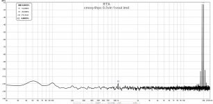
It may be interesting to check what happens to signals when the volume control attenuates the signal. By turning down 20dB, we get this result: (singal input is 1V)
Volume control at -20dB
When the volume is muted, parts of circuits and wires have a higher impedance to ground and the system becomes more sensitive to radiated noise. We also see that we get a slight upsurge of network-related noise at 150Hz, 250Hz, and 450Hz. One would have liked to see that these were not there, but since these are more than 110dB lower than the (already low) signal of 195mV, it has no effect. The voltage on these "posts" is 0.0000006V (0.6uV). It is so small that it is completely unproblematic.
To put it into perspective:
Even if this noise is amplified 22 times, which is common for a power amplifier, it will only be 13uV. That corresponds to a power of 0.000000000021W (21picoWatt).
If you have speakers with 100dB sensitivity, this will create a sound pressure of -7dB SPL 1 meter away from the speaker. It goes without saying that this is inaudible.
Noise:
These measurements were taken with the inputs shorted.
Noice floor. Volume at 0dB
Here, the noise floor is measured with a volume control of 0dB (full volume). It is an A-weighted measurement. 3.2uV total overall noise from 20Hz to 20kHz is very low. Again, it almost matches the instrument which can measure down to 1uV.
With a volume control of -16dB, the noise increases slightly up to 4.8uV. We recognize the bars from the previous measurement that appear on one channel. This time the measurement is in dBV and we see that they are at -134dBV. It corresponds to 0.2uV and, as mentioned, is far below the audible level.
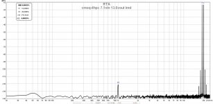
IMD
This is a difficult test where two signals (both at 2V) must be reproduced at the same time, but here too the preamp shines with very good measurements. It is over 107dB from the signals down to the first side bands. Otherwise, it's nothing. Only what should be there.
BW=80Khz. 19K and 20K@1000mV. Volume at 0dB.
All the remarks from my diy friend who measured this pre-amp is italics
Summary
Obviously, these are fantastic readings in my book and a good improvement from the last time Johnny was here.
Yes, we can measure both one and the other far down there in the depths, but it is not far off that the preamp measures as well as the measuring instrument. For all practical purposes, this preamp will be completely free of both noise and distortion at all volume settings.
Good work
Regards
J.R
Attachments
Last edited:
I am with you here, count in that the enclosures for the muse preamp(enclosures if you want the ps in another enclosure) are close to 900€ with all the work it has to be done on them.not enough money
It is not a cheap project but once you get it done you won’t need another one and if you consider you need you can always swap the gain stage like I was suggesting.
At a later time it will be more expensive to build and you will be more discouraged to build it.
I think he talks about the gamut d200.which one is that, exactly?
I seen that a while ago on your local forum while I was searching for photos of how you did the front plate on your ugs preamp.In the meantime
Very nice indeed but what kept me away was that I don’t think it has same functionality as the muse pre.
Can you confirm a few things it can do(and maybe the muse doesn’t?)
Me...tbh I followed the ugs many years but in the end I finally managed to understand the patent and implement it correctly. It didn`t take long after that and I started to follow another idea of gain stage.
I seen for a long time the thread 'What's wrong with the kiss, boy ?' but being busy with the ugs I never gave to it much importance. Once I had finished with the ugs the story had to go on so I switched to transformers as voltage amplifiers.
I started bothering ZM a few days with messages asking for clarification about how I can implement a balanced version even if there it was one already. He was kind as always and provided valuable data that in the end made me design a new pcb for my muse pre and this time it had a transformer for the vas instead the toshiba mosfets.
The most important thing on this one is NO GLOBAL FEEDBACK and can also convert se or bal to se or bal naturally, also to mention it is build with readily available parts.
If I drive this preamp with my rme dac (that puts out a lot of voltage) I can easily get the levels needed to drive power followers
A short description of what this is...it`s an Iron Pre with WHAMMY buffers on the output and using cmoq 4hpc.
Thanks to ZM again!
Attachments
@Ine this new pre of yours could easily fit ZM’s pcbs of Iron Pre. I suggest giving them a try with the cinemags. A no nfb design gives a nice and interesting sound that I never heard with my ugs which is a close clone of the one in the xs pre.
I still have to try on my muse the blowtorch which is also a no global nfb design.
When I started my journey with the preamps I started following the blowtorch design. There is Milan that has the moxtone site giving all the needed details about the blowtorch. The vas mosfets are long gone but being a lucky guy a matched octed found me recently, yeah they found me for real
I hope this winter I will stop reading a bit and put together a pcb for the blowtorch.
Depending on the needed application the blowtorch and the Iron Pre(balanced version has only 6db gain) may not have enough gain and that being when you want to drive directly a power follower. I have the rme dac that outputs a lot of swing and in this situation saves me.
Looking for "better" HiFi equipment will not lead you anywhere (except into a big sinkhole for time and money). Ask yourself what you like to have, what you like to do, and why. Then go this way... ;-)I am, to be honest, tired or running around looking for "better", so I am going to pour my heart into the UGS MUSES Scion and intended power amp, and update when I actually have something real.
What I really liked with your original project was the big volume control button with the integrated display. If you could follow up on this and maybe provide drawings, parts lists, or maybe even custom-made parts, that would be a phantastic contribution to the diyAudio community! People could use this to build their own amps with whatever audio electronics they like.
which one is that, exactly? so I can search and maybe learn trick or two ......
Its the splendid GamuT D200i/M250i .. gonna give it a few updates. The IXYS140N20P which I intend to use, have less overall capacitance compared to the APT20M19JVR originally used, so that alone should lift the performance, less of a veil I would say.
.. gonna give it a few updates. The IXYS140N20P which I intend to use, have less overall capacitance compared to the APT20M19JVR originally used, so that alone should lift the performance, less of a veil I would say.
What I really liked with your original project was the big volume control button with the integrated display. If you could follow up on this and maybe provide drawings, parts lists, or maybe even custom-made parts, that would be a fantastic contribution to the diyAudio community! People could use this to build their own amps with whatever audio electronics they like.
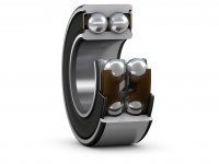
Yeah I like it as well. The Lyndorf-TacT Millenium amp which is the basis for that concept used Double Row bearings.. It was soooo smooth, I became aroused when I spun it .. - quite unique. nothing like it, before and after and even if I never owned it, I still miss it. Ofc, such a volume controller would need a custom protocol and I would need to learn how to either integrate it to the UGS Muses platform or adapt the UGS Muses platform to it, which I have not contemplated over to be honest. So I would need to do that, and I don't write code, so I need to learn that as well.
The later, as in the code, well, this can be based upon Arduino, which was the idea to begin with I think, and there are multiple ways to do so. I have a folder with lots of stuff, so I can go back to it and kickstart this endeavor. Besides the code and communication, its not terribly difficult to do, once one understand the overall function and integration...
And you are right, it would be a fantastic contribution.
The main thing is that the MUSES volume control and SuSy gain stage would continue forward with some minor updates to the choice of relay, active bridge rectifiers, proper dual mono PSU and channel separation. I would be one hell of a preamplifier.
So let me grab some coffee and contemplate how to move forward with the past... hmm ..
- quite unique. nothing like it, before and after and even if I never owned it, I still miss it. Ofc, such a volume controller would need a custom protocol and I would need to learn how to either integrate it to the UGS Muses platform or adapt the UGS Muses platform to it, which I have not contemplated over to be honest. So I would need to do that, and I don't write code, so I need to learn that as well.The later, as in the code, well, this can be based upon Arduino, which was the idea to begin with I think, and there are multiple ways to do so. I have a folder with lots of stuff, so I can go back to it and kickstart this endeavor. Besides the code and communication, its not terribly difficult to do, once one understand the overall function and integration...
And you are right, it would be a fantastic contribution.
The main thing is that the MUSES volume control and SuSy gain stage would continue forward with some minor updates to the choice of relay, active bridge rectifiers, proper dual mono PSU and channel separation. I would be one hell of a preamplifier.
So let me grab some coffee and contemplate how to move forward with the past... hmm ..
Attachments
Hi
In the meantime, I have just built this new pre-amp. ( While you are just searching and searching for the "ultimate solution")
And if that makes you happy, I am happy for you. I think its clear that you and I are different or have a different approach to what we want, In a way and I can clarify that a bit.
Approaching the preamplifier now, includes a greater understanding of what good PCB design is. The least discriminating component is overshadowed by the noisiest and the schematic can be the best in the world but it doesn't matter if the PCB is subpar and allows for interference between passive and active tracks and components.
If SINAD is greater than -80dB, usually, this is an indication of a good design. PASS's products often land in the -85dB range, so.. its good. Approaching -100dB is ofc desirable and your new pre looks to hit -112dB, so congrats. But this doesn't tell us how it sounds. A low THD is great, but for the most part, better than 0.05% is not audible and therefor nothing to go crazy about, better than 0.05% becomes an exercise in engineering only (bragging rights)
As it stands, I have the possibility to build 3 types of pre-amplifiers.
- A derivative of the UGS Muses preamplifier known as the UGS MUSES Scion, which is a digitally controlled resistor based volume attenuation with a JFet gain stage.
- An active dual mono vacuum tube fully differential gain stage (Allan Wrights) which achieves a SINAD of -112dB.
- A digitally controlled but passive inductive/magnetic volume attenuator.
You could also combine things. A balanced Allan Wright tube amp with a MUSES stepped resistor volume control, for example. If you happen to go with a transformer volume control, I could pass my Sowters on to you.As it stands, I have the possibility to build 3 types of pre-amplifiers.
Thank youIts the splendid GamuT D200i/M250i
in that case, I already learned from that amp what I was interested in, few years ago
........ gonna give it a few updates. The IXYS140N20P which I intend to use, have less overall capacitance compared to the APT20M19JVR originally used, so that alone should lift the performance, less of a veil I would say.
.......
most likely you'll not hear the difference
- Home
- Source & Line
- Analog Line Level
- UGS MUSES Scion Preamplifier