I have an analog circuit that includes three amplifiers. Two of these will be op-amps. The third one is just a unit gain buffer, non-inverting. I could design the circuit using another op-amplifier, but then there are three and there is no IC package wtih three. I could use a four-amp package and not use one amplifier. But that seems like a waste. So is there a single amplifier unity gain stable buffer for audio applications, or should I use something else altogether (FET buffer, etc.)? This is for DIY, so likely thru-hole components but SMD is not out of the question for active devices.
What are some options for the unity gain buffer?
What are some options for the unity gain buffer?
It serves as both the output stage as well as driving a feedback loop for which the impedance is 100% resistive of arbitrary value and might be 10k typically. Signal is bipolar. I probably need a high input impedance, like a FET input op-amp.
Ah, maybe using a quad op amp would not be a bad thing. I could use the extra op-amp for a first order LP or HP stage with the amplifier configured as another unity gain buffer. That way the RC filter could just be omitted.
This could allow the feature of "op-amp rolling" for those who are interested in that sort of thing!
E.g. OPA4134
This could allow the feature of "op-amp rolling" for those who are interested in that sort of thing!
E.g. OPA4134
Last edited:
Maybe a look at the actual circuit might help. If the first two stages are opamps then you might not even need a buffer tagged on the end.
The circuit does need the buffer. It's not just a voltage follower tagged on the end as you suggest.
Fair enough 🙂 If you use an opamp there is no waste using a four opamp package as you could parallel two to give increased drive ability if desired.

If you decide to use a Quad Opamp there is only one power supply needed for all four.
Question is what quality you need. Is it an audio circuit?
There are all sorts of Quad Opamps.
With FET input and bipolar input.
Also consider how much current output you need. As asked here above.
Question is what quality you need. Is it an audio circuit?
There are all sorts of Quad Opamps.
With FET input and bipolar input.
Also consider how much current output you need. As asked here above.
I have used the LT1010 which is a unity gain buffer intended to be included in the feedback loop of an op amp. It worked very well as the output for a headphone amp. I know it's an older chip that's a bit pricey. I believe there are newer chips out there for the same purpose but sorry I only have experience with the LT1010.
TL074 might do.
It is a quad with 4 opamps in one.
It has FET inputs which is good for crossovers.
It is very low price, too.
It is a quad with 4 opamps in one.
It has FET inputs which is good for crossovers.
It is very low price, too.
Not at all, done all the time. You might even think of a use for the spare amp. at some point! Having said that the widest range of opamps is available in the 8-pin dual package, so sometimes 2 dual opamps would be used rather than a quad.I could use a four-amp package and not use one amplifier. But that seems like a waste.
I use for my modular active crossover discrete buffers (JFET input) that fit on a DIP8-dual-opamp footprint.
https://www.diyaudio.com/community/...crossover-filter-solution.329458/post-5590733
https://www.diyaudio.com/community/threads/b1-turbo-on-a-chip.140488/post-5740480
https://www.diyaudio.com/community/threads/b1-turbo-on-a-chip.140488/post-6775316
But if you want ready-made solutions, why not LH0033 ?
There is also a DIY version :
https://www.diyaudio.com/community/threads/xen-zgf-portable-headphone-amplifier.286878/post-4676680
Patrick
I'd use OPA1644 which is one of the best JFET OpAmps ever for non-inverting, high source impedance buffers / gain stages. And I'd parallel two of them for the output buffer (super easy to do with the quad opamp standard pinout), using 50Ohms (or so) breakouts on each one. 3dB less OpAmp contributed noise and better load characteristics due to load sharing.I have an analog circuit that includes three amplifiers. Two of these will be op-amps. The third one is just a unit gain buffer, non-inverting. I could design the circuit using another op-amplifier, but then there are three and there is no IC package wtih three. I could use a four-amp package and not use one amplifier. But that seems like a waste.
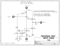
Here are some unity gain noninverting buffers which many diyAudio members have built and enjoyed.
Each one has exactly four I/O terminals: +22Vdc , Input , -22Vdc , Output . There is no connection to "ground". None at all.
You can adapt them to different supply voltages fairly easily; "Tucson" and "IPS7" demonstrate two possible approaches.
_
Each one has exactly four I/O terminals: +22Vdc , Input , -22Vdc , Output . There is no connection to "ground". None at all.
You can adapt them to different supply voltages fairly easily; "Tucson" and "IPS7" demonstrate two possible approaches.
_
Attachments


When I say "buffer" I was thinking more of a simple voltage follower...
Anyway, as I mentioned this is part of a filter circuit that uses three amplifiers. The "last" one is supposed to be a non-inverting gain stage. The problem is that for the circuit to do what I would like it to do I needed the gain be 1 or LESS, which is not possible for a non-inverting op-amp amplifier. After looking at the circuit I had the idea I could tap off the shunted input, which connects to ground via a resistor, partway to get a reduced input signal and then just use a voltage follower or other gain=1 non-inverting buffer. If I could make a simple voltage follower for this purpose like Mark shows above in ckt1 that could probably work out well. The gain I need overall is always greater than about 0.2.
But after even more head scratching I believe I have found a better way... I can replace the non-inverting op amp in the circuit with an inverting one. Now we can get our gain below 1 (or -1 if you like) with a simple op-amp inverting gain stage. But a non-inverted version of the output is needed to feed back to the middle amp in the circuit. I realized that typically there will be at least two and up to four of these circuits in series. The first amplifier in the circuit is just a simple inverting op-amp gain stage, so I can take the feedback for the first circuit AFTER that amp in the second circuit and use that for the feeback to the first circuit. If/when the gain of this inverting stage is not unity, I will need to scale the resistor in the feedback loop appropriately.
This isn't top secret stuff, so I could post the circuit and the mod I describe above. There are a couple of other points that I would also like to get input on.
To add to my previous post, the 1644' PSRR is not stellar, so very stiff and well-regulated supplies are required. Or at least a large back-to-back capacitor directly on the rail pins in an attempt to transform single rail disturbances from heavy output load currents into synchronous dual rail disturbances which represent a common-mode signal for the OpAmp. Point is, CMRR is far better than the individual pos and neg PSRR curves.
So here is the circuit I am working with. It's the Bainter notch - see attached. Amplifier K1 is an inverting stage of arbitrary gain, and K2 is a non-inverting amplifier (the details of these are not shown). The notches are not the usual symmetric form - they are the lowpass and highpass forms. See Figure 4 of this AD app note for more info:
https://www.analog.com/media/en/training-seminars/tutorials/MT-210.pdf
The application consists of 2-4 of these notch filters per HP or LP filter, the HP and LP being used in pairs (for a loudspeaker crossover). The issue is that in order to get DC unity gain in the LP form of the crossover file the gain for K2 must be less than one, which is impossible for a non-inverting op-amp based amplifier.
To get around this I came up with the modification in the image "MOD 1". I simple tapped into R5 midway to ground, to create R5A and R5B. In this way I can use a non-inverting voltage follower (gain=1) for K2. This can work just fine I guess, so it's still possibility. It's why I was asking about a simple unity gain buffer. This would leave 2 op-amps for the other amplifiers, making a nice round number per Bainter notch.
Now let's move on to the larger circuit shown in the image MOD 2, which is two notches in series with some new changes. I realized that for my application I will use N of these notch filters in series. Recall that K1 is just an inverting amplifier, so it's output is proportional to the input. I realized I could change K2 in the first notch circuit into the inverting configuration to give me gains of less than 1. But then the polarity for the feedback circuit containing R3 (from K2 to A) would be the wrong polarity. But if I move where the loop begins to the K1 output of notch circuit 2, the polarity will be corrected. But if the gain of that K2 is not unity I will also have to scale R3 proportionally to that gain so that the current is correct. Does this make sense to the reader? This modification of the R3 feedback loop would continue onwards as additional notch circuits are added in series. The last one requires an inverting amplifier to restore the correct polarity (I show this with gain of -1 but the gain is arbitrary as long as R3 is scaled to match). This would be another place where a simple voltage follower could be used.
There is another thing I realized about this circuit. The RMS voltage of the signal after amplifier A can be up to 5 times greater than for the input due to how the circuit works. This means I need 5 times the voltage headroom for A, but not for K1 or K2 amplifiers. For this reason I am considering bootstrapping this amplifier, or using one that can handle +/-24V rails, which should just be enough to work with input signal levels of a couple of volts RMS.
These circuits with N notch filters in series are used in pairs, one for the HP filter and one for the corresponding LP filter so there will always be 2N amplifiers used in the crossover. I could use dual-amplifier packages to handle the "A" amplifiers, for example, no matter the number of notch circuits that will be used in series.
Attachments


- Home
- Source & Line
- Analog Line Level
- Unity gain non-inverting buffer options?