Hi!
In these relatively quiet days around xmas. I've conceived the unity gain buffer depicted here below.
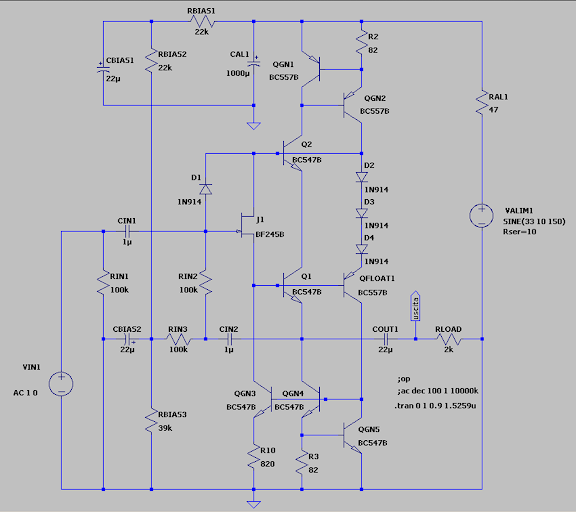
Questions is: have you yet seen some similar circuit in the past? (also not in the audio electronic field). If the answer is "yes" can you tell me vhere you seen it and from what author?
Thanks in advance
Piercarlo
In these relatively quiet days around xmas. I've conceived the unity gain buffer depicted here below.
Questions is: have you yet seen some similar circuit in the past? (also not in the audio electronic field). If the answer is "yes" can you tell me vhere you seen it and from what author?
Thanks in advance
Piercarlo
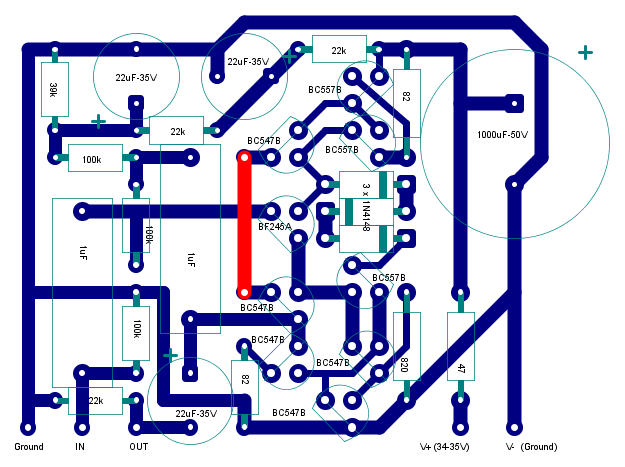
For who want to try out the schematic proposed above here below will find a track layout for build it on a small PCB, or better again, on a breadboard. BF245A (or BF245B with an Idss below 3 mA) may be replaced with any similar N channel device with an Idss comprised between 1 to 3 mA, The JFET is used in layout with swapped source and drain (operation possible with the most of general purpose JFETs) just because more straightforward to accomodate.
Happy New Year! 🙂.
Piercarlo
Happy New Year! 🙂.
Piercarlo
Last edited:

I've never seen this, it is unique, congratulations!
Hugh
Thanks! 🙂 In the next days I'll mount a pair of them for practical testing and for my use (I'm building a small integrated for headphone, in pair with a class A power amplifier derived from JLH 1969, that i named "JLH2012"). Stay tuned! ;-)
Piercarlo
This topology could be a good upgrade (front-end) for Andrea Cioffoli's Power Follower 99 - go to
http://www.audiodesignguide.com/my/Follower_99c.gif
http://www.diyaudio.com/forums/solid-state/8552-power-follower-99-sound-impressions.html
http://www.diyaudio.com/forums/pass-labs/34437-power-follower-99c-vs-zen.html
http://www.audiodesignguide.com/my/Follower_99c.gif
http://www.diyaudio.com/forums/solid-state/8552-power-follower-99-sound-impressions.html
http://www.diyaudio.com/forums/pass-labs/34437-power-follower-99c-vs-zen.html
Whats is good or special or different with regard to the performance to warrant so much complexity for just a buffer ?? It must have THD 120db below on heavy loads , extreme speed or PSRR ??.... when we can come close to that performance by using just 4 transitors and less than 1/3 the passives. Coupling caps are not well regarded in audio world either.
Whats is good or special or different with regard to the performance to warrant so much complexity for just a buffer ?? It must have THD 120db below on heavy loads , extreme speed or PSRR ??.... when we can come close to that performance by using just 4 transitors and less than 1/3 the passives. Coupling caps are not well regarded in audio world either.
Who's care of these "questions"? If I wish i can replace all just with a single op-amp connected as voltage follower... If I don't try so is because i wan't try something of different. I CAN do it and I DO it! 🙂
Piercarlo
Your circuit looks similar to Maxim's BB3553 or LH0063 (used to be Burr Brown before).
www.datasheetcatalog.org/datasheets/270/493512_DS.pdf
These are not monolithic IC but thickfilm hybrid inside.
www.datasheetcatalog.org/datasheets/270/493512_DS.pdf
These are not monolithic IC but thickfilm hybrid inside.
Before getting too involved with PCB design etc., have you made a lash-up prototype of this to make sure it all works as expected? I only mention it because spice simulations normally assume that all transistors are perfectly matched clones of one another and are closely thermally linked. In fact that all components are 'perfect'. Unless you deliberately put in variations that are more like real world scenarios. (?)
Just a thought....
Just a thought....
Before getting too involved with PCB design etc., have you made a lash-up prototype of this to make sure it all works as expected? I only mention it because spice simulations normally assume that all transistors are perfectly matched clones of one another and are closely thermally linked. In fact that all components are 'perfect'. Unless you deliberately put in variations that are more like real world scenarios. (?)
Just a thought....
I have to mount it on a breadboard of course. Obviously I DON'T assume transistor as be perfect! ;-). Some variations during simulations however has been done just for wiping out some bad surprises (that I've presented is, for now, the fifth arrangement of a more sketchy circuit).
Thanks for the thought! I appreciate it! 🙂
Piercarlo
This topology could be a good upgrade (front-end) for Andrea Cioffoli's Power Follower 99
May be, but I've conceived it as a replacement of an ordinary SIGNAL voltage follower that must be inserted between switching input network and volume potentiometer.
Piercarlo
Who's care of these "questions"? If I wish i can replace all just with a single op-amp connected as voltage follower... If I don't try so is because i wan't try something of different. I CAN do it and I DO it! 🙂
Piercarlo
Many, much more than you think, just judge by the amount of members that are actually getting involved in the thread. 😉 What does the circuit bring thats new or does better or worse than others ??
Your circuit looks similar to Maxim's BB3553 or LH0063 (used to be Burr Brown before).
www.datasheetcatalog.org/datasheets/270/493512_DS.pdf
These are not monolithic IC but thickfilm hybrid inside.
Ok, this is what I want to know. Too beautiful believe my circuit as a really new one! 🙂. The inner schematic of BB3553-LH0063 is conceptually similar to those from I started a couple of week ago. There are however a couple of improvements...
Homemodder, see you where are these improvements and what are the improvements obtained? ;-) Not the distortion, not the bandwidth, non only the SVR... (why?) ;-)
Piercarlo
Thanks for the thought! I appreciate it! 🙂
Piercarlo
Cool, I was just checking 😀
What are the improvements obtained? ;-) Not the distortion, not the bandwidth, non only the SVR... (why?) ;-)
The major real improvement is input acceptance, which is limited only by voltage supply. Once provided that Q2 and the bipolars used in current generators - QGN2, 3, 4 - have enough VCE, the Vs may any you need for your required signal acceptance, even 300 volt if you will... Of course you have to choose even the right working voltage of capacitors but this is obvious. The JFET may be any with IDSS in the range of 2-3 mA. Intrinsic output impedance (before output capacitor) should be below 10 ohm.
The improvement of SVR (and linearity) is simply a biproduct of that featured above.
Piercarlo
Last edited:
Cool, I was just checking 😀
This evening I'll look at the feature of "DropBox" for sharing files with everyone and I'll upload my schematic in LTSPICE. There is nothing here of "copyrights", "patents" and similar nuisances and the circuit can be studied - or improved: i'm not jealous!| 🙂 - by anyone want to do it.
Piercarlo
https://www.dropbox.com/s/h09yspp5i6py2z9/OltreSP-Buffe-V2.asc
Please let me know if link work fine or not.
Thanks
Piercarlo
Please let me know if link work fine or not.
Thanks
Piercarlo
Hi!
Circuit revision due to a serious design fault - a spurius SCR between a couple of transistor non revealed during simulation but (of course) readily "revealed" during breadbord testing. Here below the new schematic:

The new file for simulation on LTSPICE is downloadable at the link below.
https://www.dropbox.com/s/14iyee1jzmybfmz/OltreSP-Buffe-Revis3.asc
The new circuit is physically again under construction.
Piercarlo
Circuit revision due to a serious design fault - a spurius SCR between a couple of transistor non revealed during simulation but (of course) readily "revealed" during breadbord testing. Here below the new schematic:
The new file for simulation on LTSPICE is downloadable at the link below.
https://www.dropbox.com/s/14iyee1jzmybfmz/OltreSP-Buffe-Revis3.asc
The new circuit is physically again under construction.
Piercarlo
- Status
- Not open for further replies.
- Home
- Amplifiers
- Solid State
- Unity gain solid state buffer