With the combination of a ton of help from searching the message boards and my cave man understanding of how electronics work, I tracked the problem down to a fried Q6. Again with the help from this amazing community, including the man himself, my Aleph J is back up and running. So I'm finally enjoying (a beer and) sweet music from the combo of the Aleph J chassis and the outboard power supply.
...now, I get to start on the F5 and F6 chassis builds.

...now, I get to start on the F5 and F6 chassis builds.
I was looking at an LM723 based psu with 2N3055 when I read this comment.Tempting to use the cases with sinks as regulated supplies.
I am wondering if something like that would be a worthwhile option to explore. Has anyone looked at this or a similar regulated psu for power amps?
I am finally getting around to my external PSUs...
I'm debating using a single SpeakOn 8 conductor model and using 6 conductors for a dual mono setup. I may use 2, PowerCon models if I don't like the size of the 8 conductor SpeakOn and/or if there is a good electrical safety reason to use the PowerCon. I have reviewed specs, but I'm still a bit foggy.
The wires needing to jump the fence would be...
L GND
L V+
L V-
R GND
R V+
R V-
The advantage of using the 8 conductor SpeakOn is that I could run two more wires in the future if needed...
So, I have been reading to understand DC / AC power ratings. For switches, I could not find any applicable 'rules of thumb' for a "conversion factor". Best I can tell, there is nothing saying that if a switch is good for X VAC @ Y AC current then it will be okay for F VDC @ G DC current. It makes sense with switches that each part must be individually rated for both AC and DC. That's where the road led me, but it's slightly irrelevant, since we're not talking about switching components, and the leads will never be (dis)connected while under power; hopefully.")
However, for non-switching / wire applications, there are rules of thumb, if not absolute rules. Essentially the heating load of ACrms current is the same as DC. So, if a product is rated for 20Arms AC, then it should be okay for 20A DC. For voltage, I don't think arcing is a factor considering the voltages I'm working with (<50VDC ), correct?
I'll always follow the path of those before me, but is that reasoning generally sound? Is there anything else that should go into the consideration for a "connection mechanism"? What did I miss?
Last question for now...
Is it best practice to have:
Ground lift in PSU chassis?
Ground lift in amp chassis?
Ground lift in both chassis?
It seems to make sense to do them in the PSU chassis and have separate lifts for each channel, but I'm truly not sure. Could you / should you run a common chassis / earth GND between the two chassis and lift the ground in the amp chassis?
I can't find anything to read re: this subject. All help is appreciated.
The fate of a big box of capacitors, parts, and wiring lies in the balance....
Thanks in advance for any insights!
I'm debating using a single SpeakOn 8 conductor model and using 6 conductors for a dual mono setup. I may use 2, PowerCon models if I don't like the size of the 8 conductor SpeakOn and/or if there is a good electrical safety reason to use the PowerCon. I have reviewed specs, but I'm still a bit foggy.
The wires needing to jump the fence would be...
L GND
L V+
L V-
R GND
R V+
R V-
The advantage of using the 8 conductor SpeakOn is that I could run two more wires in the future if needed...
Speakon do 20A 3 pin connectors that would be ideal for this project.
I could not find DC ratings in the PowerCon specs. SpeakOn specifically note that they're not to be used for power delivery. I'm sure that they're both fine for the application, but I always try to piece together the puzzle.Powercon also, just check DC capability in datasheet
Though, if PL use them for XS amps, why not
So, I have been reading to understand DC / AC power ratings. For switches, I could not find any applicable 'rules of thumb' for a "conversion factor". Best I can tell, there is nothing saying that if a switch is good for X VAC @ Y AC current then it will be okay for F VDC @ G DC current. It makes sense with switches that each part must be individually rated for both AC and DC. That's where the road led me, but it's slightly irrelevant, since we're not talking about switching components, and the leads will never be (dis)connected while under power; hopefully.
However, for non-switching / wire applications, there are rules of thumb, if not absolute rules. Essentially the heating load of ACrms current is the same as DC. So, if a product is rated for 20Arms AC, then it should be okay for 20A DC. For voltage, I don't think arcing is a factor considering the voltages I'm working with (<50VDC ), correct?
I'll always follow the path of those before me, but is that reasoning generally sound? Is there anything else that should go into the consideration for a "connection mechanism"? What did I miss?
Last question for now...
Is it best practice to have:
Ground lift in PSU chassis?
Ground lift in amp chassis?
Ground lift in both chassis?
It seems to make sense to do them in the PSU chassis and have separate lifts for each channel, but I'm truly not sure. Could you / should you run a common chassis / earth GND between the two chassis and lift the ground in the amp chassis?
I can't find anything to read re: this subject. All help is appreciated.
The fate of a big box of capacitors, parts, and wiring lies in the balance....
Thanks in advance for any insights!
Neutrik XLR connectors are rated for 50VDC and many Amperes, depending on the model. They come in three pins up to seven pins. It might not be a good idea to use the three pin connectors as an uninformed user may mistake it for an audio signal connection and plug the power supply into a place where it shouldn't go.
Thanks, Ben! Definitely was not planning to use XLRs. However, given that at least one Neutrik model XLR component is rated as you describe, it gives me a lot more confidence to use the SpeakOns.
I poured over the specs, but just can't seem to find a DC rating for them. I'll cross-reference the XLR specs to see where the DC ratings hide and look in a similar place for the SpeakOns. Also, they're right in CLT ... I can give them a call on Monday if all else fails.
Mainly just trying to learn a bit.
Cheers
The information is on their website. Go to the webpage of any of their XLR connectors, click on "Technical Information", and the information is there. Or "Download Data Sheet".
I would use XLRs for DC if I needed connectors. Powercons and Speakons are not DC rated.
Neutrik says, "speakON is NOT to be used as an mains or power supply connector (AC / DC)!".
I would use XLRs for DC if I needed connectors. Powercons and Speakons are not DC rated.
Neutrik says, "speakON is NOT to be used as an mains or power supply connector (AC / DC)!".
Thanks again, Ben! I truly appreciate the insights and confirming what I had seen and not seen in the SpeakOn / PowerCon data sheets. . I hadn't really considered XLR, but now it's got me wondering... Great form factor... May be some challenging solder work, but nothing I can't handle...
For those out there that are using the SpeakOns and PowerCons in this application... other than witnessing other people using them and not having issues... What gave confidence that they'd be suitable for purpose? I don't want to toss out what may be suitable options, but I would like a bit more information on what data people used to make the choice.
Again, it's established that I lean much more toward big ol' fraidy cat than FAB. So, apologies.
I may give Neutrik a ring and ask for some insights from their side.
. I hadn't really considered XLR, but now it's got me wondering... Great form factor... May be some challenging solder work, but nothing I can't handle...For those out there that are using the SpeakOns and PowerCons in this application... other than witnessing other people using them and not having issues... What gave confidence that they'd be suitable for purpose? I don't want to toss out what may be suitable options, but I would like a bit more information on what data people used to make the choice.
Again, it's established that I lean much more toward big ol' fraidy cat than FAB. So, apologies.
I may give Neutrik a ring and ask for some insights from their side.
I have used 4 pin XLR for PSU to preamps connection before. It works great and is impossible to mix up with audio signals (XLR4 does not connect to XLR3).
I would put two XLR4 on rear of psu chassis rather than 1 x 8 pin (easier for monoblocks). Separate psu for each XLR4 if you decide to go dual mono.
I have used heavy gauge shielded wiring and connected shield to chassis at psu end only.
I would put two XLR4 on rear of psu chassis rather than 1 x 8 pin (easier for monoblocks). Separate psu for each XLR4 if you decide to go dual mono.
I have used heavy gauge shielded wiring and connected shield to chassis at psu end only.
Have used XLR for power to amps, headamps and preamps for years without any issue whatsoever.
One example includes MoFo monoblocks 24VDC @ 2A, another ZenLite headamp 48VDC @ 1.4A.
For tube gear usually use Speakon 4P for B+ up to 200VDC plus heater voltage.
Extremely reliable and easy.
Regularly use XLR for turntables as I fit the tranni outboard and feed the AC to the TT via XLR.
One example includes MoFo monoblocks 24VDC @ 2A, another ZenLite headamp 48VDC @ 1.4A.
For tube gear usually use Speakon 4P for B+ up to 200VDC plus heater voltage.
Extremely reliable and easy.
Regularly use XLR for turntables as I fit the tranni outboard and feed the AC to the TT via XLR.
Regarding using Neutrik connectors for amp DC power if you have PSU in own chassis I wrote a mail to Neutrik and asked which connector has best DC performance. They pointed out that the SpeakOn connectors was the way to go. They can handle large DC currents. So that is what I use. Also good not to use PowerCon as DC power connector to amp as you could by a mistake connect it to the mains.
I used Powercon connectors in my power supply-to-amp connections. My supply is +/- 24VDC and the Powercon are rated for high AC current. There’s no switching, so it’s just like wire connections. I only use the Powercon connectors for this purpose, so I’m not going to mix anything up. All mains connectors are IEC. If anyone else ended up with my gear… I will clearly label the connections.
I assume it’s theoretically possible someone could mix up the Speakon connections and connect speakers to the wrong spot, but we’re DIYers. Fearless amp builders and such.
The 4-pin XLR idea is interesting. That way a safety earth connection could go between the chassis.
I don’t have any ground lifts installed in my supply nor the two amps I use with it. No humming whatsoever. There’s a safety earth connection in the power supply. I still need to add such to the amp chassis.
^ von Ah - Brilliant. Thank you! Your insights re: the ground lifts are particularly interesting. I've read a ton about them, their purpose, and the various forms of implementation. One common thread seems to be that they should be used only if truly needed. I may try with and without, since this is DIY after all. My mains earth situation... seems ... to ... be ... fairly clean / good.
With that said, rules for DC applications vs. AC when one set of specs vs. the other are provided are extremely helpful. They seem to be commonplace for wire, but very few other product types, likely for very good reasons. Armed with the basics, people can make some informed decisions.
My guess (WAG) is that the connect / disconnect characteristics factor in heavily for anything rated for power use. Since (in my application) the connection will never be made or broken under power, I was/am looking for insights in that direction. More of a 'how do we go about looking at the problem' approach than 'is this specific product good for this application' approach.
This is added to the list. You and Ben have given me a higher confidence to check out XLR. I looked at the spec sheets for some products. The good news is that I could use spares. I have 4 pin XLR bits for headphone use. Alternate parts are relatively expensive, and if they don't bring additional value in terms of performance or ease of use... these climb to the top. I'll check the ratings for those exact parts accordingly to be certain. I'm not confident they're Neutrik parts until I dig them out or check my purchase history. The only downside I can foresee at the moment is soldering comparatively heavy wires in the tighter spaces, but I should be able to do it properly / safely.
Fantastic, thank you!
Perfect. That's exceptional information. I'll reach out to them also. If they'll permit me to copy or paraphrase their response and/or provide additional details, I'll post here.
I truly appreciate everyone's insights. I want to respect common sense, the law, and forum rules re: posting about anything that might surround electrical safety. However, like many new(ish) builders trying to learn, I see things that differ in posts / pics. That always makes me wonder; why did that person choose that part for that application? How do smart/informed people approach a problem from different angles? I am at the point to where I've continued to dig into spec sheets for various parts, and I'm getting to the point where some of this makes sense. When things don't jive, I head to the threads...
Regardless of advocating for a particular part as fit for use... learning what specs are truly important for an application's performance and safety is not always common sense for newer builders. Heck, if I recall correctly there are a number of people that thought certain VFETs were only designed and likely suitable for industrial switching applications ... those that chose to break that barrier did some neat work.
It's challenging and fun to learn the electrical aspects, and I'm likely going about it a bit willy nilly, but... most of the fun is putting together the Legos.
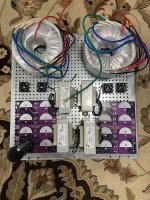
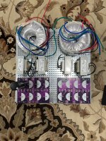
I'm fooling with layouts now. 'Going vertical' with the chokes under the filter boards and/or mounting the toroids vertically is not an option for the chassis size I'll likely go with. The baseplate in the pictures is from a 5U, 400. Floor space will be the same, but I'll likely only go 3U in height unless I have to go 4U.
Question... from a practical standpoint, should I expect any meaningful coupling from the toroids to the chokes? Are there layout considerations to keep in mind? I have and can use some of the steel cans around the toroids, but I was hoping I would not have to use them. One of the goals is to be able to swap out toroids relatively easily for various uses.
re: ground lifts - in my situation ground / earth loops between gear should be minimized due to my wiring... However, I can add them in as needed. I have thermistor only solutions a la First Watt, some diode / resistor combos a la early Pass articles, and some bridge rectifier / thermistor solutions a la F5T. Decisions... decisions. I haven't factored those into the layout yet. I'm leaning away from the standard CL60s b/c of a few things I've read (but have yet to understand) re: using them for higher power uses, how they behave under fault conditions, etc. These PSUs are going to be spread across a lot of amplifiers, so I want them to be "robust". My idea is to make them conservatively appropriate for 5A continuous current for each of the dual supplies and size the fuses accordingly per amplifier and toroid accordingly in each chassis. Note ... toroids would also be sized accordingly, and I'm running the calculations for power through the pi resistors and other components. All insights greatly appreciated!
If anyone is interested... I've also been trying to learn how to use PSUD properly to see directionally how different things impact PSUs. With a CLCRC in the PSU chassis, and with 33kuF + a 50uF motor-run in the each amp chassis... I should expect something in the 100uV range for ripple + purportedly improved performance due to localized decoupling. The whole decoupling thing has my brain spinning...
Is it overkill... sure... is it fun... YES. Am I learning a lot on the way... maybe.


Thanks everyone!
Edited to clarify fusing based on toroid (in the PSU chassis / IEC) and in the amp chassis (fused rails).
Definitely noted. All your insights are appreciated. The manufacturer has to protect themselves too and the amount of testing / certification they have to do on their side for a new 'purpose' is enormous. Then we consider product differentiation and marketing too. A hypothetical product may be 'fine' for a particular use, but for very, very good reasons it's not advertised / spec'ed for that particular use. I wouldn't expect anyone to advocate or promote.Since this is a public forum, I definitely would not promote the use of a product in a way that the manufacturer specifically advised against. There are too many litigious people in this world.
With that said, rules for DC applications vs. AC when one set of specs vs. the other are provided are extremely helpful. They seem to be commonplace for wire, but very few other product types, likely for very good reasons. Armed with the basics, people can make some informed decisions.
My guess (WAG) is that the connect / disconnect characteristics factor in heavily for anything rated for power use. Since (in my application) the connection will never be made or broken under power, I was/am looking for insights in that direction. More of a 'how do we go about looking at the problem' approach than 'is this specific product good for this application' approach.
I have used 4 pin XLR for PSU to preamps connection before. It works great and is impossible to mix up with audio signals (XLR4 does not connect to XLR3).
I would put two XLR4 on rear of psu chassis rather than 1 x 8 pin (easier for monoblocks). Separate psu for each XLR4 if you decide to go dual mono.
I have used heavy gauge shielded wiring and connected shield to chassis at psu end only.
This is added to the list. You and Ben have given me a higher confidence to check out XLR. I looked at the spec sheets for some products. The good news is that I could use spares. I have 4 pin XLR bits for headphone use. Alternate parts are relatively expensive, and if they don't bring additional value in terms of performance or ease of use... these climb to the top. I'll check the ratings for those exact parts accordingly to be certain. I'm not confident they're Neutrik parts until I dig them out or check my purchase history. The only downside I can foresee at the moment is soldering comparatively heavy wires in the tighter spaces, but I should be able to do it properly / safely.
I had definitely checked those out. Great stuff. I'm also likely stealing your grounding/earth scheme. That made the most sense to me. One of the PSUs will prominently feature purple boards... and its debut will likely be connected to an amp (or amps) prominently featuring purple boards.See post #54 for some Hirschmann connector ideas.
Have used XLR for power to amps, headamps and preamps for years without any issue whatsoever.
One example includes MoFo monoblocks 24VDC @ 2A, another ZenLite headamp 48VDC @ 1.4A.
For tube gear usually use Speakon 4P for B+ up to 200VDC plus heater voltage.
Extremely reliable and easy.
Regularly use XLR for turntables as I fit the tranni outboard and feed the AC to the TT via XLR.
Fantastic, thank you!
I wrote a mail to Neutrik and asked which connector has best DC performance. They pointed out that the SpeakOn connectors was the way to go. They can handle large DC currents. So that is what I use. Also good not to use PowerCon as DC power connector to amp as you could by a mistake connect it to the mains.
Perfect. That's exceptional information. I'll reach out to them also. If they'll permit me to copy or paraphrase their response and/or provide additional details, I'll post here.
I truly appreciate everyone's insights. I want to respect common sense, the law, and forum rules re: posting about anything that might surround electrical safety. However, like many new(ish) builders trying to learn, I see things that differ in posts / pics. That always makes me wonder; why did that person choose that part for that application? How do smart/informed people approach a problem from different angles? I am at the point to where I've continued to dig into spec sheets for various parts, and I'm getting to the point where some of this makes sense. When things don't jive, I head to the threads...
Regardless of advocating for a particular part as fit for use... learning what specs are truly important for an application's performance and safety is not always common sense for newer builders. Heck, if I recall correctly there are a number of people that thought certain VFETs were only designed and likely suitable for industrial switching applications ... those that chose to break that barrier did some neat work.
It's challenging and fun to learn the electrical aspects, and I'm likely going about it a bit willy nilly, but... most of the fun is putting together the Legos.
I'm fooling with layouts now. 'Going vertical' with the chokes under the filter boards and/or mounting the toroids vertically is not an option for the chassis size I'll likely go with. The baseplate in the pictures is from a 5U, 400. Floor space will be the same, but I'll likely only go 3U in height unless I have to go 4U.
Question... from a practical standpoint, should I expect any meaningful coupling from the toroids to the chokes? Are there layout considerations to keep in mind? I have and can use some of the steel cans around the toroids, but I was hoping I would not have to use them. One of the goals is to be able to swap out toroids relatively easily for various uses.
re: ground lifts - in my situation ground / earth loops between gear should be minimized due to my wiring... However, I can add them in as needed. I have thermistor only solutions a la First Watt, some diode / resistor combos a la early Pass articles, and some bridge rectifier / thermistor solutions a la F5T. Decisions... decisions. I haven't factored those into the layout yet. I'm leaning away from the standard CL60s b/c of a few things I've read (but have yet to understand) re: using them for higher power uses, how they behave under fault conditions, etc. These PSUs are going to be spread across a lot of amplifiers, so I want them to be "robust". My idea is to make them conservatively appropriate for 5A continuous current for each of the dual supplies and size the fuses accordingly per amplifier and toroid accordingly in each chassis. Note ... toroids would also be sized accordingly, and I'm running the calculations for power through the pi resistors and other components. All insights greatly appreciated!
If anyone is interested... I've also been trying to learn how to use PSUD properly to see directionally how different things impact PSUs. With a CLCRC in the PSU chassis, and with 33kuF + a 50uF motor-run in the each amp chassis... I should expect something in the 100uV range for ripple + purportedly improved performance due to localized decoupling. The whole decoupling thing has my brain spinning...
Is it overkill... sure... is it fun... YES. Am I learning a lot on the way... maybe.
Thanks everyone!
Edited to clarify fusing based on toroid (in the PSU chassis / IEC) and in the amp chassis (fused rails).
Attachments
Last edited:
I recommend also at least playing with alternate layouts than left/right. After some recommendations earlier in this thread, I went with the AC vs DC arrangement so the toroids and mains are on the left and the chokes and filter boards are on the right. After examining your pictures, I’m assuming that’s what you’re planning? Baseplate notches are on the sides, correct? All of my legos barely fit in a 3U 280 Galaxy, so your 500 deep plan should be fine.
Also, I may have to walk back my comments about ground lifts. My power supply (in this thread) is built from ZenMod boards, and there is a little NTC connection to the chassis ground on the filter boards. I’m assuming that’s a ground lift feature.
Also, I may have to walk back my comments about ground lifts. My power supply (in this thread) is built from ZenMod boards, and there is a little NTC connection to the chassis ground on the filter boards. I’m assuming that’s a ground lift feature.
Last edited:
^ Definitely going to play with more layouts. Thanks! Note, the chassis will likely be standard width / 400 deep / 3U. I might go with 4U if needed. I'll probably get a Pestante, since the Galaxy and Slimline won't likely give me the breathing room, and space isn't too much of a consideration. It's likely going to start life in a Dissipante 5U / 400 since I have a few already, and I can test the layouts.
It would be easier if aesthetics didn't play a role. If I were willing to have the IEC on the "back" and the DC output on the "front", the layout would be so much easier. Even I'm not willing to go that far.
So far, the considerations are:
It would be easier if aesthetics didn't play a role. If I were willing to have the IEC on the "back" and the DC output on the "front", the layout would be so much easier. Even I'm not willing to go that far.
So far, the considerations are:
- Keeping the AC lines as far away from DC as practical. There are (at least) three options I'm fooling with. Some may be combined.
- Left / Right / Center. AC up the middle with DC routed to the outputs on the right and left of the chassis.
- Left / Right - AC to one side and DC on the other.
- Top / Bottom - AC wiring under the base plate. DC on top. Use of other plates / mezzanines for extra distance and layout space.
- Distance from the toroids to chokes and/or EMI shielding for the toroids. I haven't seen this brought up before. However, with layouts for tube amps, people seem to take great care in placement of power transformers and output transformers. I know we're not dealing with the same thing ... DC smoothing choke vs. power toroid instead of output transformer vs. power transformer ... but this is where not knowing anything doesn't help too much. It seems to be a low priority, but it seems silly to squash the choke up against the toroid if it's not necessary.
- Home
- Amplifiers
- Pass Labs
- Universal Outboard Power Chassis for Pass