No gerbers but a template this time
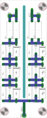
This is a template for a board with a heat sink on the back. I use this template for a lot of my projects. I choose mostly SMD parts on the top and then mount the board with the parts down and the heatsink facing up
RAD-A5723/50-AL STONECOLD - Koellichaam: geextrudeerd | met ribben; natuurlijk; L: 50mm; W: 78mm | TME - Elektronische Componenten
black anodized version.
RAD-A5723/50 STONECOLD - Koellichaam: geextrudeerd | met ribben; zwart; L: 50mm; W: 78mm | TME - Elektronische Componenten
Attachments
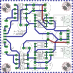
+-supply, LM317 based piggyback board
I was tired of breadboarding a complete +-15V supply every time i wanted to build something. So i made this board on a 2.54mm grid. You can just plug this board into whatever you are building. So you don't have to repeat anything.
Eagle files are also attached for anyone that wants to tweak the design.
Attachments
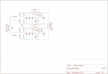
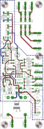
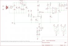
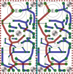
Time delays plus protection boards.
Pretty complicated boards.
Anyway there is a thyristor based over-current protection, and a TL431 based bias guard circuit that keeps the relays from switching on if there is no bias present.
Eagle files are attached for the ones that want to make alterations.
Cheers.
Pretty complicated boards.
Anyway there is a thyristor based over-current protection, and a TL431 based bias guard circuit that keeps the relays from switching on if there is no bias present.
Eagle files are attached for the ones that want to make alterations.
Cheers.
Attachments
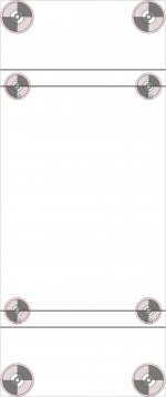
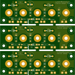
4mm jacks front panel board
This is a board for four 4mm jacks mounted on a front panel, I believe these are 3/4'' apart so a standard double banana connector fits.
Meant for supplies with or without sense connections.
there are also capactitors on the board for X2 safety capacitors to gnd.
This is a board for four 4mm jacks mounted on a front panel, I believe these are 3/4'' apart so a standard double banana connector fits.
Meant for supplies with or without sense connections.
there are also capactitors on the board for X2 safety capacitors to gnd.
Attachments
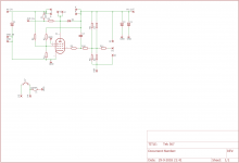
Voltage regulator positive TEK 567 based 6AU6
This is the 6AU6 error amplifier, as found in the positive output supplies of the tek567 oscilloscope.
6AU6 error amplifier, pretty straightforward.
Eagle files are attached
This is the 6AU6 error amplifier, as found in the positive output supplies of the tek567 oscilloscope.
6AU6 error amplifier, pretty straightforward.
Eagle files are attached
Attachments
There you go, this is what i had in my dropbox.
thank you, just what i need...i am fond for voltage doublers, as i make my own power traffos, a tad more convinient than full wave center tapped designes...
Active protection/clip indication
Hi V4lve lover, appreciating your contributions here!
I am looking for some sort of active protection device for my tube amps, and I like the philosophy of Patrick Turner, who compares the current in pairs of tubes, looking for an imbalance ...
Active protection
I think that is better than just triggering a failure when a hard current value is exceeded, even though that does catch runaway. The Patrick Turner solution works with fixed bias or cathode bias, and is aiming to provide an early warning that a tube is not sufficiently matched to be used in a place where tube balance matters.
I had been planning on posting a question to see if anyone had used stripboard for this circuit, to see if a standard solution around that could be created, but maybe you think this could be a PCB offering? I would be tempted with a GB for that, along with a maida style regulator for G2 voltages.
Cheers, Richard
Hi Richard,
I have been thinking of something among similar lines, my solution would be akin to a led bargraph that moves left or right with imbalance coupled with a hard cut-off for the high voltage under certain circumstances. One problem with this approach is that it becomes rather complex quickly, furthermore there is a downside to measuring cathode current over true anode current measurements. That is that the G2 current varies from tube to tube somewhat, therefore bias measurements by means of measuring the cathode current are not 100% accurate.
However circuits like these are no substitute for proper design philosophy. I prefer to use a mix of cathode bias and fixed bias, this seems to be the best of both worlds in practical implementation.
Tony,
If you send me a datasheet of the four terminal capacitors you are referring to i can see what i can do.
Hi v4lve lover,
this is what i mean: perhaps your eagle library have those already..
this is what i mean: perhaps your eagle library have those already..
An externally hosted image should be here but it was not working when we last tested it.
Attachments
Last edited:
Hi V4lve,
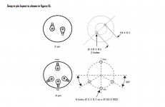
sorry for late reply, this is what i have in mind....
rectifiers are off boards, and cap banks are in series, options to both 2 pin and 4 pin snap-in caps....with bleeder resistors, 5 watt size, and film bypass caps....you posted a similar one but all 8 caps are paralleled...led options to indicate power would be nice....
40 mm diameter cans max.....thanks in advance
An externally hosted image should be here but it was not working when we last tested it.
Last edited:
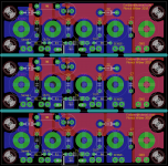
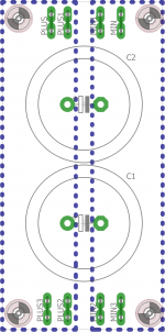
Dual power supply boards DC heaters+ regulator?
Thanks for the support.
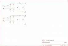
Heres another interesting board for double CRC for low voltage.
Suggested diodes for low voltage are SB540 skottkeys.
Thanks for the support.
Heres another interesting board for double CRC for low voltage.
Suggested diodes for low voltage are SB540 skottkeys.
Attachments
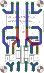
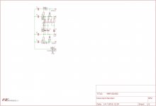
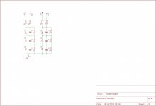
negative half of tube SS bridge rectifier configuration
These boards where meant for the negative part of a solid state tube hybrid bridge, for example EY500 X2 for the positive half rectification and one of these boards for the negative half.
These boards where meant for the negative part of a solid state tube hybrid bridge, for example EY500 X2 for the positive half rectification and one of these boards for the negative half.
Attachments
- Home
- Amplifiers
- Tubes / Valves
- V4lve lover's free Gerbers thread