Velleman used to offer two tube power amplifier kits, the K4040 and K8010. Both are out of production as of now, and even the manuals are no longer available. Some of the web pages that discuss the amplifiers are no longer available, and the information becomes harder to find.
Since I own a K4040, built from a kit back in 2009, and just revised it slightly, I'd like to open this thread to keep the manuals, mods, and other relevant information easily available for reference.
I start with the two original assembly manuals from Velleman. These used to be publicly available on Velleman's web site, so I hope there it's not a problem attaching them to this post.
In the next posts, I will publish the original and modded schematics and mods I have been able to find and use, links to some resources that are still available, as well as some pictures.
Attachments
K4040 schematic and output and power transformers
The schematic for the K4040 is quite conventional: Two triode amplification stages, a cathodyne phase splitter, and a big and hot qual of EL34s in untralinear more driving the output transformer. The feedback is fed into the cathode of the second triode stage; the whole amplifier is inverting.
The output toroidal transformer has Raa of 1800 ohm (15:1 turn ratio between anode-anode primary and 8ohm secondary). The ultralinear taps are 33%. The secondary has a 4ohm tap that is also used for feedback.
The power supply has a whole bunch of nice features not frequently seen in pother designs. It includes:
- A separate standby power supply based on a separate small PC mounted transformer (in the upper left corner of the power supply schematic, marked "TRANSFORMER")
- A thee way switch selecting between OFF (only standby power is live), STB (main power TRANSFO2 transformer is live, heaters are on, but anode supply is reduced) and full ON
- Soft start (Q1)
- Delay between powering on heaters and applying full anode voltage (Q2-Q4); it also controls the muting relays that short the amplifier's input
- Output tube bias meter based around LM3914 and a LED array
Attachments


K4040 IronAudio mods
Over the years, there has been a lot of discussion of what to change in the K4040. One of the more comprehensive lists was posted in 2001 on ironaudio.com, now defunct. The list is still available on web.archive.org (thank you gemenakis for providing the link!), but here it is for your convenience:
Over the years, there has been a lot of discussion of what to change in the K4040. One of the more comprehensive lists was posted in 2001 on ironaudio.com, now defunct. The list is still available on web.archive.org (thank you gemenakis for providing the link!), but here it is for your convenience:
One thing I would add to the list is getting two matched quads of tubes. The original Svetlana EL34s included with the kit were unmatched, and their distortion performance was unpredictable even with properly adjusted bias. Matching (preferably curve matching) each quad is important - some tube stores will do it for free.Velleman K4040 Stereo Tube Amplifier
Updated 8-September-2001
The K4040 uses 11 tubes
Eight EL34s, Two 12AX7s and a 12AU7
Basic Setup
I have found the following tubes produce the richest soudstage, the greatest clarity, and the best realism:
EL34s
Svetlana
I haven't tried the JJs but hear that they are very good.
12AX7s
Mullard CV4004/M8137
They give extreme dynamics and clarity.
The JJ ECC83Ss are a very good choice but they lack some of the dynamics and detail of the Mullards.
Sovtek 12AX7LPSs are good but a bit bright.
12AU7 (V11)
JAN Sylvania 6189W
It is extremely articulate, supports the dynamics and clarity of the CV4004/M8137s, and introduces NO hum.
The Telefunken ECC82 is almost as good.
The JJ ECC82 is a good choice.
The stock JAN Philips 6189W is OK.
I have also tried various JAN 6072As - they are good but all introduce hum.
A poor choice for V11 will introduce hum into the signal path, choose well!
The following tweaks work for me, no guarantee they'll work for you.
First Level Tweaks
ZD1
ZD1 changed from a 7V to a 5V zener to prevent RY4 from opening during a power sag and causing damage to R105-R108 and surrounding area. VERY important!
R4
R4 changed from a 1K to a 2.2K to slightly increase RY4's close time and to compensate for the lower value on ZD1.
Cathode Resistors
R97,R98,R99,R100,R101,R102,R103,R104, replaced with 10 ohm, 1%, 1W metal film resistors for more accurate bias settings.
Second Level Tweaks
WIMA Coupling Capacitors
The 22nf C5,C6,C9,C11,C12,C13,C14,C15,C19,C20,C21,C22 coupling capacitors replaced with 63nf WIMA polypropylenes to increase the amp's bass response.
Filter Capacitors
C39, C40, C41, C42 replaced with 470uf - 450V caps. C37 and C38 replaced with two of the old 220uf caps pulled from C39-C42, to support greater bass response.
Input connectors and cabling
I removed the input PCB and replaced it with high quality components including isolated heavy duty gold input connectors, RGS-316 silver plated coax input cabling and a .047uf oil filled capacitor for the shield bypass.
Left Channel V11 to C9 Signal Trace
I discovered that the slight hum I was picking up in the left channel was mitigated by running the V11 pin 6 to C9 signal through coax. After removing J11 and J15, I ran a piece of RGS-316 between the right hole for J15 over to the left hole for J11 and attached the shield to J12.
Third Level Tweaks
The WILD side - Four KT88 Conversion
KT88s by JJ
I placed the JJ KT88s in the V2, V4, V5 and V7 positions. I'm idling the KT88s at 64.5ma and still using the standard bias adjustment by replacing R97, R100, R102 and R103 with matched 6.2 ohm, 2%, 1W metal film resistors.
Because the KT88 bases are too large for the holes in the top cover plate, I raised the four KT88 sockets by using 1/2" standoffs so that the tube sockets would be flush with the top surface of the cover. This required rewiring the sockets. I then capped the four unused holes with chrome plated snap-in faucet hole covers.
Also I have put the KT88s in triode mode by disconnecting, insulating, and securing the brown and green wires (transformer screen taps) from both terminal blocks. Then I connected the four screen terminals to their respective plate terminals using short jumpers.
The results are nothing short of pure sonic excellence! The JJ KT88s REALLY deliver! Yes, they have blue glass. This modified K4040 has a vastly improved sound over my unmodified K4040.
The Next Tweak?
The EXTREME side - an eight KT88 Conversion
I have been told the power and output transformers should handle it!
However, the reason I went with KT88s is so I could approximate the power output of eight EL34s and not have to use a parallel circuit which inherently adds distortion. Therefore I am staying with the above design. But for raw power output, the eight KT88 design would be the way to go.
Last edited:
Hi alexcp,
it might be of interest that the K4040 had a predecessor called K4000. I built it from a kit about 25 to 30 years ago, still own it and also have the printed manual including building instructions. I remember there was a Dutch website dealing with mods before the year 2000 already. Maybe I have a printout or dump of that site somewhere, too.
IIRC, basically the K4040 is just the K4000 plus an added biasing metering circuit and somefancy chrome rings where the EL34s protrude through the chassis.
Regards, Tom
Attachments


Thank you Tom! I remember seeing the manual for the K4000 many years ago. And yours is a good looking amp!
May I ask you to please scan and post the schematic? It is curious, since K4040 is 90W/ch, but the front page of K4000 manual says 2x200W. Does it also use the output tubes in ultralinear or pentode mode?
Update: just found a K4000 manual online and attach it here. It is ultralinear, 200W is “music power”.
Attachments
Last edited:
If an ECC83 cathodyne is enough for this , it means that the rest of phase splitters and more powerfull tubes for drivers are useless 
Last edited:
I had a K4040 changed the el34's for 6550's. My main comment on the original design was the driver stage was very slew rate limited so a 10KHz sinewave at 1/2 power would look more like a triangle wave at the speaker. The first stage also did give heater hum with its un-bypassed cathode resistor. Good kit though.
Thank you for adding Velleman information.
I regard mirror surfaces a design mistake in tube power amps.
Heat radiation is prevented on even two sides of this amp and
heat just "thrown back" to the tubes. As a consequence valve
temperatures are unduly high.
I regard mirror surfaces a design mistake in tube power amps.
Heat radiation is prevented on even two sides of this amp and
heat just "thrown back" to the tubes. As a consequence valve
temperatures are unduly high.
It is a lot of power dissipation. Each tube dissipates 6.3V x 1.5A = 10W on the heater and 380V x 40mA = 15W on anode, 25W in total. Eight tubes in total dissipate 200W, and there is not that much space between them.
Even more radical mods
In 2006, ecsdesign published here on diyAudio a much more radical way to modify the K4040, which I ended up implementing. His original posts are here and here - if the links take you to a wrong place, they are posts #1029 and #1037 on the thread "Building the ultimate NOS DAC using TDA1541A".
For convenience, here is his first post (the second post will follow):
Little bit off topic here, since you are talking about tube amplifiers, guess what I have been doing? I needed a tube amplifier to test both the sonic resonators and the octal D-I DAC, but I didn't have one. I didn't want to spend a lot of money on a High-End tube amplifier, and there wasn't time to design one from scratch, so I decided to buy a K4040 kit (shame on me). I knew there were some design problems, and I might need to do some minor modding in order to get the sound right. Some JJ KT77's were ordered, just in case...
Then the kit arrived, it didn't have the ILP transformers I hoped for, the EL34's were from Svetlana, the ECC83's from Sovtec and the ECC82 from Electro Harmonics. The housing looked very impressive with the massive chrome plates, even the feet and the decoration rings for the tubes were chrome. It comes with a a huge single-sided PCB. I planned to use Beyschlag metal film resistors instead of the cheap carbon resistors, Spectrol cermet's for bias adjustment and Panasonic electrolytic capacitors. After a few hours the PCB was assembled, wiring the EL34 sockets cost a lot of time. Then it took me another day to squeeze-in the transformers and wiring as there was very little space.
I continued with the bias adjustment, there is a LED indicator for this, but it's readout wasn't very good, a lot of LED's burning and flashing at the same time, so I had to solder a 100nF across the LM3914 input to get it working correctly. Finally it was time to listen to this 2 X 90W rms tube monster, well in fact the sound it produced wasn't that good. Perhaps the Svetlana's needed some burning-in time, but after burning-in one full day without significant sound improvement I lost my patience. Measurements showed relatively high distortion and a huge peak at around 40KHz.
Next lot's of different tube brands were tested, but it became clear to me, the design wasn't optimal, so I could prepare myself for some serious modding. Starting with the input stage, what's a ECC82 doing here? I replaced it with a JJ ECC83 and changed the resistor values for maximum linear drive. A concertina phase splitter using a ECC83 to drive 4 X EL34 ?? out it went and replaced with a modified Schmitt phase splitter with a constant current source (2 X J508 in parallel) to ensure fully symmetrical drive. The ECC83 wasn't capable of driving 4 EL34's, so I replaced it with JJ ECC81. The EL34's were replaced with JJ KT77, next the 22nF coupling cap's were replaced with LCR 100nF/1KV polypropylene capacitors, yes tubee, coupling cap's can make a world of difference. Oh yes, the overall feedback was removed, only using local feedback. The bias voltage was stabilized with a 47V zenerdiode (22K series resistor lowered to 10K).
After these modifications there wasn't much left of the original K4040 design, but the sound quality was stunning, what a difference. The K4040 turned into a beautiful sounding High-End power amplifier. Distortion is much lower, it sounds crystal clear, transparent and open, with a deep impressive bass and a wonderful sounding midrange. Unbelievable what a few modifications can do.
Last edited:
Second post by ecsdesign on his K4040 mods:
The phase splitter used in the K4040 is often referred to as concertina phase splitter, when looking at the schematic diagram it resembles a cathodyne phase splitter. One output at the annode, one at the cathode. With this setup there are problems like low gain, linearity and load sensibility.
I used a Schmidt phase splitter, the modification is a added 4mA constant current source. The Schmidt phase splitter is very linear, easy to adjust, stable and has low distortion. The outputs of the Schmidt phase splitter are both on the annodes, the constant current source lowers distortion.
I added a schematic diagram of the modifications I made, this makes it a bit clearer, the same reference numbers were used where possible, but I may have missed one, only the left channel is shown. The following list gives a overview of the modifications made:
1) 100nF/63V capacitor across D23, this will suppress hum on the bias readout.
2) R5 and R10 lowered to 10K, C29,31 increased to 100uF/100V, 47V zenerdiode across C29 and C31 (cathode to plus), this will stabilize the bias voltage, regardless of transformer load.
3) High-quality potentiometers for bias adjustment (Bourns or Spectrol)
4) V11 changed to ECC83, improved sound quality (ECC83 from phase splitter can be used)
5) R61=100k, R62=100K, R59=27k, R60=27K, R11=6K8, R16=6K8, this will set the correct gain for V11.
6) C5=100nF/1KV, C9=100nF/1KV polypropylene (Farnell P/N 106367)
7) Cathodyne phase splitter replaced by modified Schmidt phasesplitter (see diagram). J508 and J509 are 2mA constant current sources (Farnell P/N 9549951). V9 changed to ECC81 (RS P/N 5011342).
8) C11...14, C19...22 changed to 100nF/1KV polypropylene (Farnell P/N 106367)
9) RV1...4, RV5...8 changed to Bourns or Spectrol.
10) R89...96 changed to 1K Ohm 1W.
11) R32...34, R51, R29...31 and R38 changed to 1.5 K Ohm.
12) Overall feedback removed, only using local feedback.
13) Svetlana EL34's replaced by JJ KT77, clearer sound, better bass and trebles.
14) 3.3nF/5KV capacitors were placed in parallell with D11...D14 to suppress switch noise.
15) ZD1=3.9V zener instead of 7V5 (solves mains brownout problem, this is already modified in new kits)
The EL34 sockets may cause bad connections when a tube with bigger pin diameter has been inserted once, due to bent contacts, pin 5 should be checked carefully as it is also used to set the bias current. Higher quality tube sockets could be used.
All carbon film resistors were replaced with Beyschlag 1% metal film resistors for stability and lower noise.
Always be carefull working on high-voltage circuits, wait until the electrolytic capacitors are fully discharged. When modifications are made, always double check before switching-on the power.
Finishing touch, the chrome decorative rings may scratch the large chrome plate, so I applied protective self adhesive polycarbonate sheet (used to protect front panels) to avoid scratches.
Attachments

If this schematic is correct an EL34 tube will go full current when the bias pot looses contact.
Cathode resistor will be destroyed and probably screen resistor also.
It should be possible to find a quick fix for it.
Cathode resistor will be destroyed and probably screen resistor also.
It should be possible to find a quick fix for it.
The schematic is correct. A fix is probably possible but not without modifying the board. Using better quality trimpots should help.If this schematic is correct an EL34 tube will go full current when the bias pot looses contact.
Cathode resistor will be destroyed and probably screen resistor also.
It should be possible to find a quick fix for it.
Fix : jumper the wipers to the -VL end of the pot, probably decrease
the series resistor by a parallel one if the adjustment range suffers.
Edit : additional resistors in series from -VL to pot are required also.
the series resistor by a parallel one if the adjustment range suffers.
Edit : additional resistors in series from -VL to pot are required also.
Last edited:
ecdesigns's modification removes the global feedback from K4040. Without feedback, K4040 has a higher input sensitivity, more hum and noise, and depends on matching the output tubes between the channels.
There are two ways to re-introduce global feedback after ecdesigns's mod:
I tested both and ended up implementing the second option. Attached is the final schematic. CF (47pF) helps to improve the phase margin. CC (22pF) was required for stability of the left channel, which is connected to V11 via a long trace across the PCB, with two wire jumpers.
With feedback, the distortion and hum are reduced, and the sensitivity in in line with the sources like CD players, giving 2Vrms full scale.
There are two ways to re-introduce global feedback after ecdesigns's mod:
- Apply it to the grid of V9B (see the schematic attached to post #12) by lifting the bottom end of CA from the ground and connecting it to the feedback divider. This option is easier to wire and has less stability issues, but it does not enclose V11 in the feedback loop and, as the sensitivity of the rest of the amplifier decreases, makes V11 work harder, increasing distortion.
- Apply it to the cathodes of V11. This is trickier to introduce from the stability viewpoint but improves overall linearity.
I tested both and ended up implementing the second option. Attached is the final schematic. CF (47pF) helps to improve the phase margin. CC (22pF) was required for stability of the left channel, which is connected to V11 via a long trace across the PCB, with two wire jumpers.
With feedback, the distortion and hum are reduced, and the sensitivity in in line with the sources like CD players, giving 2Vrms full scale.
Attachments

In 2005, Jan Veiset published a different way to modify the phase splitter. Unfortunately, his website (www.veiset.net) is gone. A copy is available on web.archive.com, but it is in Norwegian with black letters on black background 😱
Here is a slightly edited Google translation:
Original circuit description
The phase inverter is built around the double triode ECC83. The first half is used exclusively for gain, just under + 40dBu, and the other half is a split-load phase inverter. The advantage of split-load is that it is a simple and tidy construction, and they are easy to balance. The disadvantage is the lack of the ability to deliver (high) voltage.
A slightly more technical review
The triode that works as an amplifier has the following working points: Ia = 0.65mA, Ug = 0.65v (blue curve). The stage works with a relatively high anode load, 390k and the input impedance to the next step is very high, partly due to positive feedback. All in all, the stage works atop maximize the gain.
The next stage is a little harder to understand. It is basically a completely traditional split-load phase inverter, but without the negative bias on the grid! Although the grid leakage is not very high (820k), it is possible that negative bias builds up when the signal is applied. In any case, it looks like this half of the tube is running very hard. Which is also necessary to be able to deliver enough voltage to the output stage.
For driving of the power stage (4xEL34, B+ 420v) approx. 25 volts RMS is needed. If we add 50% to the headroom, the phase inverter should be able to deliver around 37 volts RMS or 100 volts p-p. Both theory and measurements show that the stage has very small margins. The phase inverter is and will be a bottleneck in this construction.
New phase inverter
To avoid too many changes, I keep ECC83, move away from the split-load inverter and replace it with a paraphase splitter. The static working point is the same for both triodes, Ia = 1.4mA, Ug = 1.4v (red curve). I lose some gain, estimated gain with R1 in the next stage around 130k is about + 33dBu or a loss of about 6dB compared to the original solution. Umax is designed for 40v RMS with Ub = 365v.
At the same time I change the coupling capacitors from 22nF to 220nF. This will lower the open loop frequency response from around -3dB @ 30Hz down to -3dB @ 3Hz. Hopefully this gives better control in the bass area.
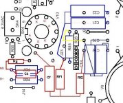
Practical implementation
The practical implementation was easy, as I had prepared by drawing the new components on a copy of the top of the PCB.
After some soldering work, it was time for measurements. The result was above all expectations, about 55v rms before phase splitter clipping. That is, there is plenty of headroom here.
Picture before and after are attached.
Working drawing
Here is the working drawing I worked from. If you want to upgrade the phase inverter in your K4040, it should work well if you follow the following recipe:
1) Remove the following components:
J23
R86, R87, R88, R23
C15, C19, C20, C21, C22
2) Cut the PCB trace between R87 and C19 / C20
3) Fit the following components:
Rg (680k)
R86, R88 (100k)
R87 (1k)
Rf1 (593k 560k + 33k)
Rf2 (560k)
C19, C20, C21, C22 (220nF)
Cf (100nF)
Ck (100uF)
4) Connect R88 and C19 / C20 on the underside of the PCB (yellow line)
5) Do the same for the other channel.
6) Screw the amplifier together and turn up the volume.
Here is a slightly edited Google translation:
Original circuit description
The phase inverter is built around the double triode ECC83. The first half is used exclusively for gain, just under + 40dBu, and the other half is a split-load phase inverter. The advantage of split-load is that it is a simple and tidy construction, and they are easy to balance. The disadvantage is the lack of the ability to deliver (high) voltage.
A slightly more technical review
The triode that works as an amplifier has the following working points: Ia = 0.65mA, Ug = 0.65v (blue curve). The stage works with a relatively high anode load, 390k and the input impedance to the next step is very high, partly due to positive feedback. All in all, the stage works atop maximize the gain.
The next stage is a little harder to understand. It is basically a completely traditional split-load phase inverter, but without the negative bias on the grid! Although the grid leakage is not very high (820k), it is possible that negative bias builds up when the signal is applied. In any case, it looks like this half of the tube is running very hard. Which is also necessary to be able to deliver enough voltage to the output stage.
For driving of the power stage (4xEL34, B+ 420v) approx. 25 volts RMS is needed. If we add 50% to the headroom, the phase inverter should be able to deliver around 37 volts RMS or 100 volts p-p. Both theory and measurements show that the stage has very small margins. The phase inverter is and will be a bottleneck in this construction.
New phase inverter
To avoid too many changes, I keep ECC83, move away from the split-load inverter and replace it with a paraphase splitter. The static working point is the same for both triodes, Ia = 1.4mA, Ug = 1.4v (red curve). I lose some gain, estimated gain with R1 in the next stage around 130k is about + 33dBu or a loss of about 6dB compared to the original solution. Umax is designed for 40v RMS with Ub = 365v.
At the same time I change the coupling capacitors from 22nF to 220nF. This will lower the open loop frequency response from around -3dB @ 30Hz down to -3dB @ 3Hz. Hopefully this gives better control in the bass area.
Practical implementation
The practical implementation was easy, as I had prepared by drawing the new components on a copy of the top of the PCB.
After some soldering work, it was time for measurements. The result was above all expectations, about 55v rms before phase splitter clipping. That is, there is plenty of headroom here.
Picture before and after are attached.
Working drawing
Here is the working drawing I worked from. If you want to upgrade the phase inverter in your K4040, it should work well if you follow the following recipe:
1) Remove the following components:
J23
R86, R87, R88, R23
C15, C19, C20, C21, C22
2) Cut the PCB trace between R87 and C19 / C20
3) Fit the following components:
Rg (680k)
R86, R88 (100k)
R87 (1k)
Rf1 (593k 560k + 33k)
Rf2 (560k)
C19, C20, C21, C22 (220nF)
Cf (100nF)
Ck (100uF)
4) Connect R88 and C19 / C20 on the underside of the PCB (yellow line)
5) Do the same for the other channel.
6) Screw the amplifier together and turn up the volume.
Attachments


thanks so much to alexcp for all the information he provides on this protentional great sounding amp... and for being a gentleman!
Thanks a lot!
Thanks a lot!
- Home
- Amplifiers
- Tubes / Valves
- Velleman K4040 build and mods