Hi everyone.
I ask for your help to understand where the problem lies and possibly how to try to solve it once and for all.
I'm dealing with the classic, usual Fullbridge amplifier Chinese copy of the Brazilian sounddigital.
It seems that there are various Chinese brands that copy them.
One in particular is really excellent and builds amplifiers for a handful of brands here in Italy, while others appear to be very poor, as they have (factory new) enormous and very annoying background hiss if used on the front speakers.
I've compared all 3 models (sounddigital, good Chinese brand and bad Chinese brand) and they really look the same, except for a few things, but they basically work the same.
The thing that immediately struck me are the output inductors, which are different between the 2 Chinese brands.
I'll try to attach 2 images of a good Chinese 5000 and a poor Chinese 5000, to show the "differences" that I struggle to find.
The tests that have been done on the bad Chinese amplifier:
1) the background hiss seems to decrease significantly if the supply voltage is </=10v, so I thought that by regulating the feedback circuit to have a coincident rail even at 14.8v I would have solved the problem, but not it solves.
2) I thought of a preamplifier problem, but separating it from the rest of the amplifier by removing the "DC decoupling cap" I correctly separated the preamplifier from the amplifier, but the hiss remains.
3) I tried to level and strengthen the power supply of the entire preamplification, but the hiss remains.
4) I tried to somehow modify the values of the filter capacitors on the amplification stage, but the problem remains, indeed it could get worse (I did this test, because I noticed that the values of the Chinese amplifier are different from those of the sounddigital original)
5) I tried to install additional 6.8uf 400V ceramic capacitors, as close as possible on the pins of the output mosfets, but the problem is not solved.
After doing all these USELESS tests, I'm seriously starting to think that the fault lies with the output inductors, which are literally terrible.
But I ask you, maybe someone has already understood something, and wants to help me.
As you can see from the photos, although all 3 are 5000w, the sounddigital and the good chinese copy, use only one power terminal block and a single output terminal block, also, the diodes are to220 format, while in the bad chinese copy, we have even 2 power terminal blocks, a double output terminal block and the diodes are in TO247 format.
The latter would be very favorable factors to a bad Chinese copy, if it weren't for the fact that, in practice, the amplifier is worthless.
A thousand thanks.
Attachments


Hi Perry.
Unfortunately, the good copy is no longer in my possession, as I handed it over to the customer after repairing it.
But from memory, I remember that the Carrier of that amplifier is about 112khz (khz more, khz less).
The bad Chinese copy has a carrier of about 145khz and the original sounddigital has a carrier of 102/104khz.
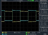
What I have been able to observe is that curiously, the soundigital and the good Chinese copy have a duty cycle (on the output switching frequency) equal to 50%, while the bad Chinese copy has a wider duty cycle, that is, observing the switching frequency with the oscilloscope, I find that the positive edge of the waveform lasts longer than the negative edge of the waveform.
Also, I forgot to check if the noise was visible on the oscilloscope, but I guess so.
Since it's a fullbridge, to see it, can I use GND BATT as a reference and alternately look at one half-bridge at a time? or should I behave exactly like in a half bridge amplifier?
Unfortunately, the good copy is no longer in my possession, as I handed it over to the customer after repairing it.
But from memory, I remember that the Carrier of that amplifier is about 112khz (khz more, khz less).
The bad Chinese copy has a carrier of about 145khz and the original sounddigital has a carrier of 102/104khz.
What I have been able to observe is that curiously, the soundigital and the good Chinese copy have a duty cycle (on the output switching frequency) equal to 50%, while the bad Chinese copy has a wider duty cycle, that is, observing the switching frequency with the oscilloscope, I find that the positive edge of the waveform lasts longer than the negative edge of the waveform.
Also, I forgot to check if the noise was visible on the oscilloscope, but I guess so.
Since it's a fullbridge, to see it, can I use GND BATT as a reference and alternately look at one half-bridge at a time? or should I behave exactly like in a half bridge amplifier?
If all you have is a mains powered scope, use it in differential mode.
The duty cycle at idle is whatever it has to be to get the DC offset across the speaker terminals to 0.000v (or as close as it can get).
The duty cycle at idle is whatever it has to be to get the DC offset across the speaker terminals to 0.000v (or as close as it can get).
When this amp was delivered to me, both loaded and unloaded, it had 0.287v output, but it sounded smooth.
Then I adjusted the trimmer to adjust the output dc offset, and now I have about 10mV without load and 0 with load, so the offset is now practically zero, but the duty cycle shown remains the same as before, i.e. greater than 50 %, dare I say 60 or 63%.
Could this thing be causing the background hiss?
At this point, I would like to ask if a poorly designed inductor could also impact the duty cycle.
Anything much more than 50% would be a concern. Are the drive signals for the high and low-side both good?
Does the amp pop when turning on or off?
Does the amp pop when turning on or off?
Both before and after adjusting the dc offset, a small "tick" is clearly heard when switching on but nothing to worry about, when switching off I don't hear anything relevant.
I'll check the signals on the gates.
I'll check the signals on the gates.


Do you have a diagram for this circuit?
That scope cap is odd because the waveforms are offset but the ground references are aligned. With an analog scope, you align the traces to ground and the waveforms will be aligned. Sometimes, digital scopes fight you on this.
That scope cap is odd because the waveforms are offset but the ground references are aligned. With an analog scope, you align the traces to ground and the waveforms will be aligned. Sometimes, digital scopes fight you on this.
What is the DC voltage (to at least 3 decimal places) on pins 8, 9 and 10 of OPA1?
Did adjusting the DC offset pot get the duty cycle to 50% for either or both of the carriers?
Did adjusting the DC offset pot get the duty cycle to 50% for either or both of the carriers?
Hi Perry, In this picture I show you, you can observe the switching frequency of both half amps of an original sounddigital 5000 (which is how I expect it to be).
Then I made the measurement you asked me, and I was able to compare them also to the original sounddigital.
This is the situation:
The bad Chinese copy (referring to battery ground):
OPA1 pin 8: 8.42v
OPA1 pin 9: 8.34v
OPA1 pin 10: 8.30v
...essentially the same...
The sounddigital amplifier :
OPA1 pin 8: 9.91v
OPA1 pin 9: 9.91v
OPA1 pin 10: 10.03v (when I touch this pin with the tip of the multimeter, also the sounddigital begins to make a rustle and at that moment observing the switching frequency, almost the same thing happens as in the Chinese copy).
Attachments
You need to find the reason that the waveforms are offset. You know that they can't be in reality if they're swinging between ground and rail voltage.
For the chinese amp, Did adjusting the DC offset pot get the duty cycle to 50% for either or both of the carriers?
What's the full part number for the OPA1 IC?
For the chinese amp, Did adjusting the DC offset pot get the duty cycle to 50% for either or both of the carriers?
What's the full part number for the OPA1 IC?
The waveforms are probably staggered due to the probes that are old and maybe mismatched, I've already bought new probes, but I still have to use them because I thought I'd use these until they died.
The DC offset adjustment trimmer does not affect the waveform in any way, both in the Chinese amplifier and in the sounddigital.
The only thing that varies if I touch the trimmer is the DC output voltage, acting on the trimmer to bring the output voltage to 0 or as close to 0, both in the Chinese amplifier and in the sounddigital.
There must be something else regulating the duty cycle.
The part number for OPA and OPA1 is definitely TL074, PROC1 is definitely a LM319.
The input offset of the SD amp is about what I'd expect to see. The 80mv offset of the chinese amp sees excessive, especially considering that the output isn't more significant. Are the diodes in the feedback leaky?
Have you replaced the op-amp?
Have you replaced the op-amp?
I have not replaced any integrated circuits because the problem encountered on this unit is known by many.
I have 3 identical amps here, from the same supplier, made by the same factory, with the same problem.
I think it's a design flaw rather than a flaw of a simple op amp.
Having said that, I will not take anything for granted, I will replace both the TL074 and the LM319, and for safety, I will replace the two diodes on the "COMPARATOR AND ERROR AMP" and I will do these operations one at a time, to understand which replacement will solve or it will alleviate the problem.
- Home
- General Interest
- Car Audio
- Very annoying hiss with a Chinese SOUNDIGITAL copy!