Draki, thank you for your concern. You think I haven't read the manual? I read it 10 times in the last six months. But, just like kimmosto throws up his hands and says 'I wrote everything', so I spread my hands and say 'I read everything'! Answer the question. There are four speakers and a bass reflex. Two speakers have their own volumes (boxes), two another have the same volume. On the drivers tab, how many speakers should there be? How many impedance responses do my speakers need to make?
^ I hear you ")
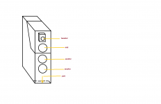
Can you please describe the exact layout of the system? Is it W(separate)+W(separate)+ MM(shared volume, are these run together or as 0.5 config) + T?
Anyway, for the two drivers in a shared volume:
- measure impedance as used (the two drivers in parallel I guess);
- measure nearfield of one driver, with both drivers connected, the other muffled (pillow, blanket etc);
- the nearfield should be corrected for the baffle step in the diffraction tool (and merged with the nearfield of the BR, if any, in the calculator tool);
- the farfield measured for one driver only, with only that driver connected; you can short the other one;
- in calculator merge this farfiled with the nearfiled + BR (if any)
- now you have the final merged near+far for one driver;
- in the xo, generate two drivers (in parallel, if that is how they are connected), each with this final response (same for both);
- apply impedance to each driver but scale it by 2.0 since the measured was with both in parallel already;
- apply each driver's X,Y coordinates
Hope this makes sense.
Last edited:
- in the xo, generate two drivers (in parallel, if that is how they are connected), each with this final response (same for both)
the responses of the same drivers located in the same volume, one above the other, as I drew, should not be the same. They should be almost the same, but different. Due to the location of the box elements in relation to the drivers.
About this was my question:
- measure impedance as used (the two drivers in parallel I guess);
- apply impedance to each driver but scale it by 2.0 since the measured was with both in parallel already;
Thank you.
Attachments
IMO, the simpler method would be to treat the doubled drivers as individuals, i.e., different. (You could name them Twin1 and Twin2). Thus each driver would ultimately have its own impedance measurement and its own frequency data.
When measuring the one driver, short-circuit the voice coil of the other. That is all there is to it.
When measuring the one driver, short-circuit the voice coil of the other. That is all there is to it.
^That is valid for far field measurements only. All drivers sharing the same box volume MUST be connected to amplifier to get correct near field and impedance response result. Correct impedance result at LF is important especially if you add compensation for impedance peak(s) at LF.
Impedance response is easiest to scale with Scale text box, but also possible to split to separate responses with the main program or Calculator (or Excel). No need to split.
Damping the other driver with pillow while near field measurements should be just isolating. Not damping or braking the cone which could change response of measured driver.
Last edited:
the responses of the same drivers located in the same volume, one above the other, as I drew, should not be the same. They should be almost the same, but different. Due to the location of the box elements in relation to the drivers.
They are not exactly the same but effect to simulated total is not big because sound balance is - or at least should be designed with on-axis, listening window, few individual off-axis, power response and early reflection responses.
Whole vertical plane affects to result more than small difference in vertical position, but also measurements in vertical plane are possible skip with circular radiators by allowing flat axial response and very small hump in power response at mid-range.
Last edited:
When measuring the one driver, short-circuit the voice coil of the other. That is all there is to it.
This will lead to errors. During operation of the first driver, the second (with a shorted voice coil) will fluctuate due to the changing air pressure inside the box. This will smooth out (damp) the vibrations of the first. In normal working condition, both drivers simultaneously create pressure or vacuum inside the box.
Just to clarify, there is no real need to extend the scale range up to positive 1800 degrees.
To illustrate, the first attachment shows a standard wrapped phase response. The second attachment shows the same response with the phase unwrapped.
This is "standard" view. But maybe one should try to takeaway the vertical lines? Or gray them down significantly. After all, they don't really exist so can be said to be a false description. Try and see have it comes out?
//
^That is valid for far field measurements only. All drivers sharing the same box volume MUST be connected to amplifier to get correct near field and impedance response result. Correct impedance result at LF is important especially if you add compensation for impedance peak(s) at LF.
The point of shorting the other driver is that you are loading it in the same way that the amplifier's output stage would, so impedance as seen by the measured driver includes the effect of the acoustic loading of the non-measured driver. (If left open, that driver would act like a passive radiator and thus change the LF tuning).
This will lead to errors. During operation of the first driver, the second (with a shorted voice coil) will fluctuate due to the changing air pressure inside the box. This will smooth out (damp) the vibrations of the first. In normal working condition, both drivers simultaneously create pressure or vacuum inside the box.
See my reply above.
The point of shorting the other driver is that you are loading it in the same way that the amplifier's output stage would, so impedance as seen by the measured driver includes the effect of the acoustic loading of the non-measured driver. (If left open, that driver would act like a passive radiator and thus change the LF tuning).
Wrong. Amplifier's output stage is eliminated from the result by calculating ratio from output voltage to terminal voltage. In addition that most of measurement app manufacturer's recommend constant current measurement with quite high series resistance.
Even more important is that tuning of driver+box system changes compared to final application if you measure impedance from one driver only while the others in shared box volume are shorted. There are two error sources: double volume and other driver is semi-passive radiator damped electrically with Q >> 0 due to losses in voice coil e.g. Re. Cone is neither rigid wall nor active moving along the others.
After all, they don't really exist
You can not know that. When infinite signals are summed in frequency domain with complex math, wrapped phase is the result. Unwrapped phase is result of mathematical process assuming that jump from < -90 deg to > +90 deg is wrap of -360 deg and vice versa.
Anyway, there is no problem to split curve to two...numerous segments with different color or line type or both, but that will reduce performance. I just have to decide which is more important; performance or less intelligent individuals who don't understand what phase wrapping means.
Last edited:
Wrong. Amplifier's output stage is eliminated from the result by calculating ratio from output voltage to terminal voltage. In addition that most of measurement app manufacturer's recommend constant current measurement with quite high series resistance.
You misunderstand my reference to "amplifier's output stage". This is not in relation to the driver under test, but to how the other drivers will be connected, hypothetically.
Even more important is that tuning of driver+box system changes compared to final application if you measure impedance from one driver only while the others in shared box volume are shorted. There are two error sources: double volume and other driver is semi-passive radiator damped electrically with Q >> 0 due to losses in voice coil e.g. Re. Cone is neither rigid wall nor active moving along the others.
I don't understand the double volume factor you mention. However, I concede that damping of the non-measured drivers due to the impedance of the source signal (zero amplitude here) may be a factor.
I will test this (not soon, though).
I don't understand the double volume factor you mention.
If you have two drivers in shared volume of 22 liters (drivers are connected either in series or parallel in final application), each driver finally sees 11 liters i.e. frequency and impedance response (with scaling multiplier) equals to volume of 11 liters with single driver.
But if you short one driver and measure the other either near field or impedance, measured driver sees total 22 liters with semi-passive radiator. So this method gives very wrong result at low frequencies. Impedance response is okay at high frequencies where system resonance does not affect anymore, but that is not what I would call universal and accurate method.
I don't have the time to post all graphs immediately, but here are my findings, briefly:
I used two Vifa mid-bass drivers in a sealed enclosure of 8.8 litres. I used the mic-in-box method to measure LF response.
Observations:
1. LF response of the drivers connected in parallel was similar to that of the configuration where one driver was driven while the other was shorted out. The latter had around 6dB lower amplitude.
2. Apart from shorting the non-driven driver, I also tested it with resistors inserted instead of a short-circuit. The resistors ranged: 0R0 (short-circuit), 1R0, 2R2, 4R7, 22R, 39R. As the resistance was increased, the SPL curve lost its shape, relative to the parallel case, and the impedance curve developed a double hump. The 1R0 resistor yielded the closest match to the SPL curve of the paralleled drivers, albeit 6dB lower.
3. Simulations in WinISD and VituixCAD for two parallel drivers predicted an impedance peak at 92Hz. The measured Z peak of the parallel drivers was 91Hz (good). The single-driver-with-other-driver-shorted configuration had its resonant peak at 69Hz.
No need to post here because impedance response shows that result is wrong for sure, and in-box method measures sum of active and semi-passive driver. It's not near field measurement referred in documentation.
Anyway, match in in-box acoustical response with some shorting resistor > 0 Ohms and in-box measurement is funny, but based on luck. Because the other driver is semi-passive and in-box measures sum of both drivers, high-pass slope is steeper due to acoustical short-cut at LF and magnitude above system resonance is higher with >0 Ohms than with short-cut due to lower braking force i.e. higher Q of semi-passive resonator.
So you succeeded to create electrically damped passive radiator producing close to equal total SPL with closed box with very different system resonance, but impedance response reveals that they are not alike.
Last edited:
Thanks for indulging me.
I believe the case for same drivers sharing an enclosure - if they are connected the same way (series or parallel) - is straight-forward: one can measure their respective impedances with them connected that way. I do suspect, though, that things won't hold up when the drivers have different networks (filters) between them and the amplifier, such as with a 2.5-way crossover. The impedance that the respective drivers see looking back towards the source will be different. One would have to take care that impedance on the low frequency side is similar, at least.
I believe the case for same drivers sharing an enclosure - if they are connected the same way (series or parallel) - is straight-forward: one can measure their respective impedances with them connected that way. I do suspect, though, that things won't hold up when the drivers have different networks (filters) between them and the amplifier, such as with a 2.5-way crossover. The impedance that the respective drivers see looking back towards the source will be different. One would have to take care that impedance on the low frequency side is similar, at least.
...things won't hold up when the drivers have different networks (filters) between them and the amplifier, such as with a 2.5-way crossover. The impedance that the respective drivers see looking back towards the source will be different.
Unfortunately that is true. System resonance changes when difference between electrical circuits supplying the voice coils increases. Usually we just trust that very small or equal Rdc of inductors in passive low pass filters keep changes insignificant enough.
We could also measure features of system resonance with asymmetrical source impedance. Close to same method with eliminating protection circuit for true ribbons. I'm so lazy and voice in my head (called common sense) says that it's not worth
- Home
- Design & Build
- Software Tools
- VituixCAD