May we ask for the Circuit Diagram, and the how this looks at the back of the PCB (PCB Diagram)? We're using it for school, and having the circuit diagram, and its connection in the PCB will be a great help. Thank You!!!

Last edited:
Hello!
That appears to be a PCB made from the circuit in this thread -
You will need to look for the most appropriate version, at a glance it’s not the initial design, but a later variant.
That appears to be a PCB made from the circuit in this thread -
You will need to look for the most appropriate version, at a glance it’s not the initial design, but a later variant.
Formula3HP
Here is an Amplifier using 3 transistors.
It has low distortion.
Gain is x4 which should be good for 32 Ohm headphones.
Power supply could be one LM317 set at 12 VDC.
All resistors can be 0.6 Watt.
Formula3HP
The latest version is in https://www.diyaudio.com/community/...p-amplifier-with-low-dist.359267/post-7055776
- lineup
- Replies: 557
- Forum: Headphone Systems
Last edited:
Post #29 seems correct.
Hi Marin.
The prototype had been running fine for a while with a different power supply so I have progressed with this one.
I left the circuit as is other than adding an LM317 regulator for the PSU. Minimum ~18v in and regulated down to 12v. I haven't had any issues driving it with either mobile phone or DAC, so I left the input alone for now.
I went ahead and got PCBs made with the following scheme:
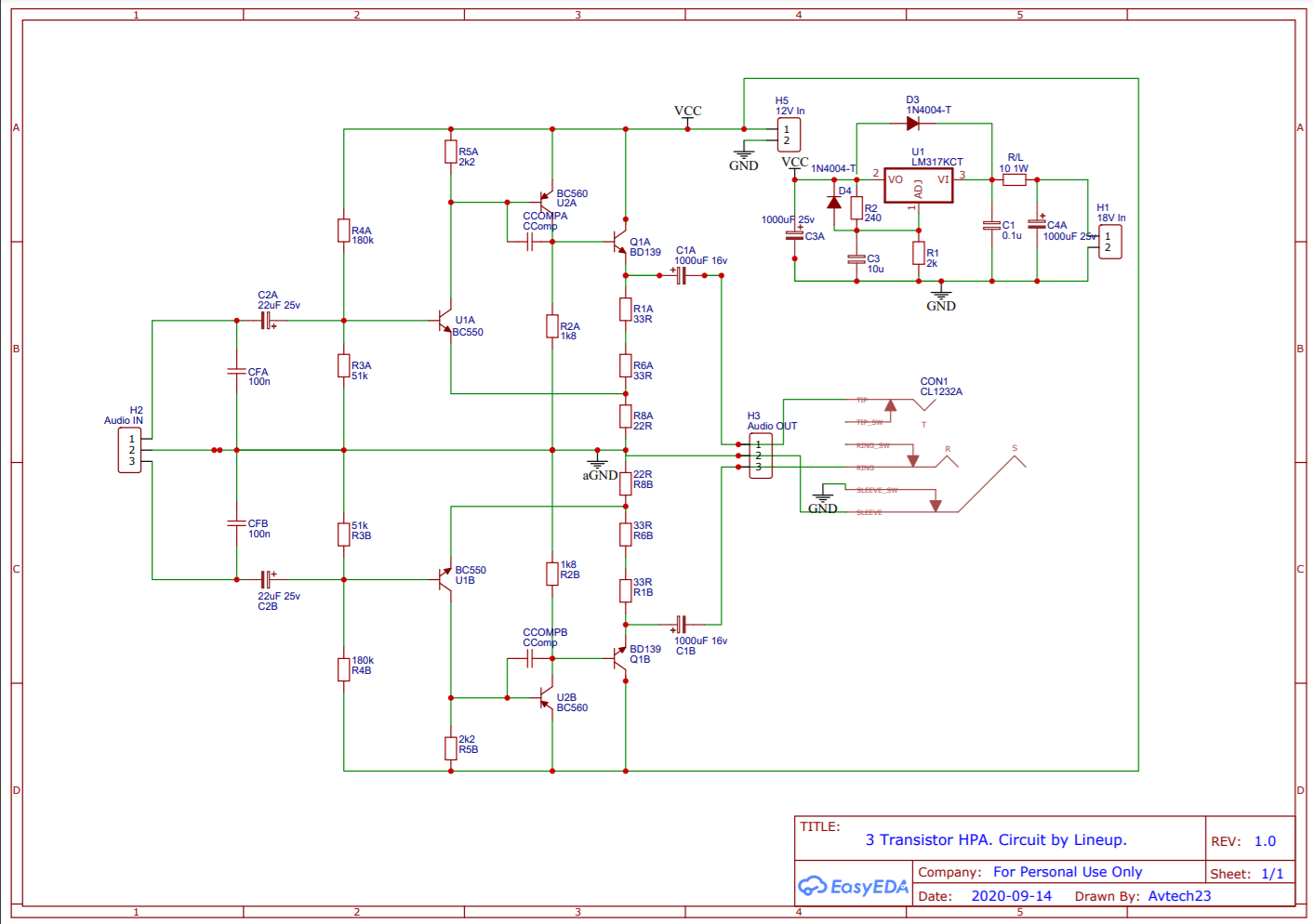
This was the final layout...
The prototype had been running fine for a while with a different power supply so I have progressed with this one.
I left the circuit as is other than adding an LM317 regulator for the PSU. Minimum ~18v in and regulated down to 12v. I haven't had any issues driving it with either mobile phone or DAC, so I left the input alone for now.
I went ahead and got PCBs made with the following scheme:
This was the final layout...