Informative simulation. It would be nice to have a "real" opamp simulation for OPA1612 and OPA1656 (and OPA2134?). That would be helpful for this sort of work.
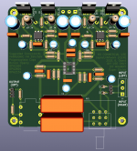
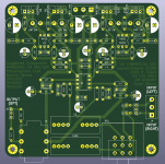
I have attached the latest layout and schematic. Getting ready to order soon. Since this shrunk 10cm x 10cm board is only $2 to order I am hoping that it will allow many others to DIY. As a result I really would like to get the design and layout right. If anyone has a moment to look over it I would appreciate it. My hope is for first pass success and I would like the design/layout to be well done.
I have attached the latest layout and schematic. Getting ready to order soon. Since this shrunk 10cm x 10cm board is only $2 to order I am hoping that it will allow many others to DIY. As a result I really would like to get the design and layout right. If anyone has a moment to look over it I would appreciate it. My hope is for first pass success and I would like the design/layout to be well done.
Attachments


Kozard,
Thanks for doing this. It clearly opens up options to use tricked out power supplies, headphone connectors, potentiometers/attenuators and opamps that diy’ers like to roll with, in addition to direct coupling if your source is free of dc.
Best,
Anand.
Thanks for doing this. It clearly opens up options to use tricked out power supplies, headphone connectors, potentiometers/attenuators and opamps that diy’ers like to roll with, in addition to direct coupling if your source is free of dc.
Best,
Anand.
Last edited:
This is a very nice board! Thank you for making it. 
Looking forward to hearing from you after you build a prototype if the layout works well. (I suspect it will, but these things need to be tested… remember the original whammy board had 1 major and 2 minor revisions before it was great.)
Looking forward to hearing from you after you build a prototype if the layout works well. (I suspect it will, but these things need to be tested… remember the original whammy board had 1 major and 2 minor revisions before it was great.)
It was not considered making the layout as dual mono with 2 x single op-amps?
Next step could then be to make the PCB so two single PSUs could be used for 100% dual mono?
Next step could then be to make the PCB so two single PSUs could be used for 100% dual mono?
…but essentially all headphones have a common ground. (Balanced headphones excluded, but that’s a fad.)
Ok, yes that is true. But for preamp use it could make sense.....maybe...
I think my headphones has a single mini-jack pr cup so in theory it would be possible to make it as 100% dual mono. This would require a wire from each cup and 2 x single jack connectors in Whammy? .....but I have never seen any done that and not very practical.
I think my headphones has a single mini-jack pr cup so in theory it would be possible to make it as 100% dual mono. This would require a wire from each cup and 2 x single jack connectors in Whammy? .....but I have never seen any done that and not very practical.

I'd buy dual mono boards in a second. All my cans are 4 pin LXR terminated. Because why wouldn't you?
Well $2 gets you 5 boards at JLCPCB.
So perhaps later I can make a derivative which is a mono board. I would want to prove out the first (stereo) design before thinking about that.
Would need to think about the connectors, etc. I assume the potentiometer would be deleted and would be external? What would you want to see for the connectors?
Use a single opamp footprint? (More limiting.) Or a dual using only one side?
Last edited:
At least one of the projects here on this site, offers builders the option to use either a single opamp (example: LT1122) OR a dual opamp (example: LM4562) just by plugging into different sockets. see photo
As you might already know, the LT1122 is not available in both single and dual; it's single only. And the LM4562 is not available as a single; it's dual only. With two sockets, a board can accommodate either of them.
_
As you might already know, the LT1122 is not available in both single and dual; it's single only. And the LM4562 is not available as a single; it's dual only. With two sockets, a board can accommodate either of them.
_
Attachments

Well $2 gets you 5 boards at JLCPCB.
I'm 97% noob when it comes to amps so I'll wait for a working prototype. Otherwise the likelihood of smoke is also 97%.
What would you want to see for the connectors?
No preference.
As there's much empty space in the board layout as per #4221, perhaps some of this could be used to add alternative 4 pin connections for Mark's Input Stage option pcbs developed for the M2x amplifier (seen above) ...
It has to be open loop variants of the boards (not unity gain) as Whammy has a global NFB loop to achieve very low output impedance and also a bit of voltage gain?
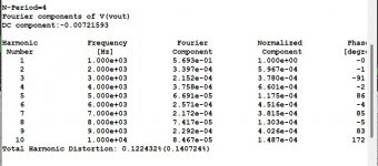
Attached are what should be the final version. I plan to order the PCB tomorrow after checking again later today and again tomorrow morning. If you see any issues please let me know!
Attachments

If one day the PCB layout was made to accommodate "single" op-amps could Waynes 2018 line stage be used as "op-amp(s)" if the feedback loop was opened (R16 lifted on linestage) so the Whammy global NFB loop was connected to the "lifted" R16 on linestage?
R16 goes to what would be the inverting input of the op-amp?
Then Whammy would be 2 x Wayne?
Wonder if anything of this could be understood.......
R16 goes to what would be the inverting input of the op-amp?
Then Whammy would be 2 x Wayne?
Wonder if anything of this could be understood.......
I would also like to have two of these boards. Do you also ship to Germany?
The boards were ordered this morning and it will take 3-4 weeks for them to arrive (airmail) and be tested. If they are ok the idea is that anyone can order them from JLCPCB website for $2 plus the shipping fee. It is an easy website to use. Just upload the gerber file .zip archive, use all defaults on the PCB options, add to card and checkout/pay.
If one day the PCB layout was made to accommodate "single" op-amps could Waynes 2018 line stage be used as "op-amp(s)" if the feedback loop was opened (R16 lifted on linestage) so the Whammy global NFB loop was connected to the "lifted" R16 on linestage?
R16 goes to what would be the inverting input of the op-amp?
Then Whammy would be 2 x Wayne?
Wonder if anything of this could be understood.......
I am not familiar with Wayne's linestage. Perhaps he can comment?

- Home
- Amplifiers
- Pass Labs
- "WHAMMY" Pass DIY headphone amp guide