Hi Ken,
Not sure what is meant here by 2x OS.
Is it repeating the same sample twice, or is a digital filter included after having stuffed the original data with zero’s ?
If the second option is meant, why then using a seventh order filter to reconstruct the insignificant HF losses by the zero hold sinc with 2xOS ?
Hans
It should be fixed now.Thanks! I downloaded it. I got a message for corrupted files but seems usable. I'll try it!
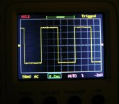
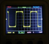
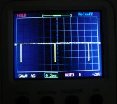
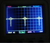
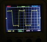
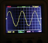
Track #2 is full scale ~1kHz square wave, Track #4 is ~1kHz one sample period width pulse train, Track #5 is 22.05 kHz full scale square wave. On a NOS DAC without an analog filter the signals are perfect square waves or pulses, no ringing or rounded edges. (Full scale is incompatible with ringing, it causes clipping in most OS).
Just for the record.
It was mentioned several times that a slew rate limit in the current to voltage converter behind the DAC may cause serious distortion whereas a proper RC response does not.
Suppose the time between samples is T.
What percentage of the time should the D/A converter have reached a stable current output to prevent a distortion contribution and what should be the minimum requirement for the slew rate and BW to prevent input overload when using an op-amp for the current to voltage converter, expressed in values of T, assuming a max output voltage of 2Vrms.
As known, this may play an important role in the NOS discussion but the acceptable limits haven’t been quantified so far.
Hans
Very nice! Let's see how it goes.It should be fixed now.
Track #2 is full scale ~1kHz square wave, Track #4 is ~1kHz one sample period width pulse train, Track #5 is 22.05 kHz full scale square wave. On a NOS DAC without an analog filter the signals are perfect square waves or pulses, no ringing or rounded edges. (Full scale is incompatible with ringing, it causes clipping in most OS).
Hi Ken,
Not sure what is meant here by 2x OS.
Is it repeating the same sample twice, or is a digital filter included after having stuffed the original data with zero’s ?
If the second option is meant, why then using a seventh order filter to reconstruct the insignificant HF losses by the zero hold sinc with 2xOS ?Hans
Those are good questions, Hans. A more proper notation for 2xOS, would have been, 2FS. Which, of course, simply means twice the Fundamental Sample rate. So, 2x44.1KHz = 88.2KHz. Upsamplers are digital FIR interpolation-filters. Which typically utilize the zero-stuffing technique to calculate the interpolated values. At 2FS, for each sample that holds actual data, the sample immediately after it is blanked to zero. The stream of alternating data/zero samples then are sent through the low-pass filter, which calculates interpolated values to replace the zero samples. I also recall reading somewhere that the core construct filter of Foobar (the SoX utility) is a fully convolving Windowed-SINC design.
My understanding is that Abraxalito (Richard) is utilizing Foobar as an external OS digital reconstruction filter, transmitting an 2FS (2xOS) 88.2KHz sample rate SPDIF signal to his DAC, which contains no OS internal filter of it's own, and is otherwise NOS. His 7th order passive reconstruction filter is what he was utilizing prior to the Foobar upsampling. I don't believe that he uses the analog filter in conjunction with the Foobar digital upsampling filter.
PCM1794 can process real NOS; it can do this if pins 11 and 12 are tied to Vcc. Then, it processes whatever comes via I2S. So, if you feed it a "raw" file (for example, a non-oversampled WAV file that was created by ripping the CD track, and played by JRiver with its DSP disabled), it will be working in true NOS. PCM1794 is not a true R-2R DAC, but it can work in true NOS mode, where its internal digital filter is bypassed.
The sigma-delta modulator inside the PCM1794 has to have a higher sample rate to work properly, so in that sense it's still oversampled, even though you don't use the digital interpolating filter. Hence the use of terms like quasi-NOS.
Ken Newton said:...Which typically utilize the zero-stuffing technique to calculate the interpolated values. At 2FS, for each sample that holds actual data, the sample immediately after it is blanked to zero. The stream of alternating data/zero samples then are sent through the low-pass filter, which calculates interpolated values to replace the zero samples...
RESTATED FOR CLARITY: ... an additional new sample is inserted after each existing input data sample, and given a value of zero. There are now two samples, where there was a single sample before. One with sample data, and one with a zero value. So, three are twice the number samples per second now, as before.
Last edited:
I don't believe that he uses the analog filter in conjunction with the Foobar digital upsampling filter.
I don't remove the 7th order filter when listening with foobar (SoX) upsampling. Some time ago I did create an optimized 7th order filter for use with upsampling but I'm not sure where I put it. The NOS 7th order filter is designed primarily to have a steep transition band at the expense of ultimate stop-band rejection. A filter optimized for use with upsampling would improve the stop-band attenuation (from 68kHz up) and largely disregard the transition band steepness.
I don't remove the 7th order filter when listening with foobar (SoX) upsampling. Some time ago I did create an optimized 7th order filter for use with upsampling but I'm not sure where I put it. The NOS 7th order filter is designed primarily to have a steep transition band at the expense of ultimate stop-band rejection. A filter optimized for use with upsampling would improve the stop-band attenuation (from 68kHz up) and largely disregard the transition band steepness.
Thanks, for that clarification.
i assume, that you compared the upsampled sound with, and without the 7th order filter? What did you hear that convinced you to keep the 7th order analog filter in circuit along with the upsampling?
Last edited:
PCM1794 can process real NOS; it can do this if pins 11 and 12 are tied to Vcc. Then, it processes whatever comes via I2S. So, if you feed it a "raw" file (for example, a non-oversampled WAV file that was created by ripping the CD track, and played by JRiver with its DSP disabled), it will be working in true NOS. PCM1794 is not a true R-2R DAC, but it can work in true NOS mode, where its internal digital filter is bypassed.
EDIT: forgot to attach the screen capture.
Yes,
Just to add that for NOS mode dac can only accept Right justified format.
Just for the record.
It was mentioned several times that a slew rate limit in the current to voltage converter behind the DAC may cause serious distortion whereas a proper RC response does not.
Suppose the time between samples is T.
What percentage of the time should the D/A converter have reached a stable current output to prevent a distortion contribution and what should be the minimum requirement for the slew rate and BW to prevent input overload when using an op-amp for the current to voltage converter, expressed in values of T, assuming a max output voltage of 2Vrms.
As known, this may play an important role in the NOS discussion but the acceptable limits haven’t been quantified so far.
Hans
This is something that should be cleared IMO to exclude mediocre I\V converters from the equation as being a main cause of the difference between OS and NOS.
I’ll put it in LTSpice and try come back with answers.
Hans
I have tried many "passive" I/V converters in the past (and still using these now) but changing to NOS from OS will make a difference even then, that is my experience ...
Interesting Chord Dave review:
Chord Dave FPGA DAC - YouTube
Interesting Chord Dave review:
Chord Dave FPGA DAC - YouTube
Just for the record.
It was mentioned several times that a slew rate limit in the current to voltage converter behind the DAC may cause serious distortion whereas a proper RC response does not.
Suppose the time between samples is T.
What percentage of the time should the D/A converter have reached a stable current output to prevent a distortion contribution and what should be the minimum requirement for the slew rate and BW to prevent input overload when using an op-amp for the current to voltage converter, expressed in values of T, assuming a max output voltage of 2Vrms.
As known, this may play an important role in the NOS discussion but the acceptable limits haven’t been quantified so far.
Hans
Settling-time is not a fixed percentage of a variable T, but rather is specified as a constant time figurer no matter the period of T. By definition, the settling-time is the time it takes for the DAC's output signal to reach and maintain a level of +/- one-half an LSB after a sample change is initiated. For example, the TDA1541 features a data sheet specified settling-time of 1uS. Therefore, the S/H circuit should hold the prior output signal value for at least 1uS after each DAC update. The required minimum S/H circuit hold-time (waiting time) will depend on a given DAC, because settling-time varies by DAC model.
You only need include DAC settling-time in a S/H calculation for a passive resistor I/V circuit. To include the slewing limit and other A.C. errors of a given active I/V amplifier, it's easiest if you have an amplifier settling-time figure provided, which is sometimes conveniently specified in a given op-amp's data sheet. Shown either as a set of figures or graphed, in terms of % error-band.
I'll use the arbitrary figures below, just for illustration.
=================================
DAC settling-time (DST) = 1uS
I/V Amp settling-time (AST) = 2uS
S/H Wait time calculation (It's simply the Pythagorean Theorem):
-------------------------------------------------------------------------
SQRT(DST^2 + AST^2) = Total minimum S/H wait before update time.
SQRT(1x1 + 2x2)
SQRT(1 + 4)
SQRT(5)
= 2.236uS
That is just to compute the minimum S/H hold-time after a DAC update.
Do not add low-pass filtering anywhere between the DAC's output and the S/H circuit's input. You don't want to integrate the settling-time error in to the signal, the objective of the S/H is to completely exclude the signal error energy by gating the signal until it has settled. In addition, adding any output filter prior to the S/H gate will increase the signal's settling-time, thereby increasing the minimum S/H waiting time required. You want the garbage (error) part of the signal to disappear as rapidly as possible, leaving only the accurate signal value for forwarding.
Ken,
I’m not that much interested in settling time but in distortion caused by slewrate limitation and input overload of a an active I/V converter something you don’t have when using a RC network.
When using a S&H behind the filter, things are getting a different perspective, but I’m not aware of commercial products having this.
So my intention is to find the minimum slew rate for an active filter to make this S&H superfluous.
Hans
NOSvsOS measurements
@Icsaszar's test file tracks #2, #4 and #5 NOS/OS pairs. Also tried @MarcelVG's intersample overshoot test. I get clipping only with OS mode regardless the settings of the digital volume control... BTW I'm using the digital volume control in my main system. Yes, I've read the backround theory of this and I aimed for a gain structure that allows to keep the volume within the upper 1/3 of its range. I don't feel I'm loosing anything.
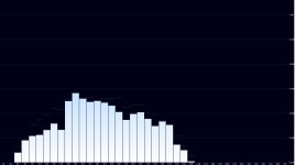
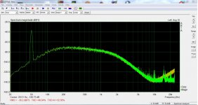
Last, I used Alan Parson and Stephen Court-Sound Check CD track #6 "Low Mid Band 200Hz-1kHz and Phase Check". Attached how it seems on Foobar and in FFT -OS is green. Not sure if the particular is audible but it demonstrates what I was thinking about possible images projecting below the Nyquist frequency into the audio band.
Listening impression tomorrow evening...
@Icsaszar's test file tracks #2, #4 and #5 NOS/OS pairs. Also tried @MarcelVG's intersample overshoot test. I get clipping only with OS mode regardless the settings of the digital volume control... BTW I'm using the digital volume control in my main system. Yes, I've read the backround theory of this and I aimed for a gain structure that allows to keep the volume within the upper 1/3 of its range. I don't feel I'm loosing anything.
Last, I used Alan Parson and Stephen Court-Sound Check CD track #6 "Low Mid Band 200Hz-1kHz and Phase Check". Attached how it seems on Foobar and in FFT -OS is green. Not sure if the particular is audible but it demonstrates what I was thinking about possible images projecting below the Nyquist frequency into the audio band.
Listening impression tomorrow evening...
Attachments
Ken,
I’m not that much interested in settling time but in distortion caused by slewrate limitation and input overload of a an active I/V converter something you don’t have when using a RC network.
When using a S&H behind the filter, things are getting a different perspective, but I’m not aware of commercial products having this.
So my intention is to find the minimum slew rate for an active filter to make this S&H superfluous.
Hans
The DAC's analog output is ALSO slew-rate limited. The DAC chip's transisitions between samples is slew rate limited. Frans Sessink's S/H presentation primarily, but not only, had to do with slew-rate distortions produced by the DAC chip itslef.
The RC exponential settling of the S/H circuit is strictly for the benefit of analog circuits succeeding the S/H. It allows the dynamic-errors of the DAC and of the I/V to be blocked and replaced by the relatively much lower static-errors of those same circuit blocks. This means that the slewing distortions and other AC errors of the DAC chip AND of the I/V circuit become non-issues.
Last edited:
Ken,
Thanks for your reaction.
Yes I fully agree that a D/A needs some time to get to it's final value, as also mentioned by me a few postings back
Question is, is this like a pure LP filter response in which case it can be neglected, or is it caused by slew rate limitation.
With an active conversion the output voltage stays put because of going into a virtual gnd, whereas a passive network makes the D/A output to produce a voltage.
Only in the first case a slew rate limit and an input overload can produce non linearities.
So I want to know the minimum slew rate for the combination of D/A plus Active I/V converter to get some feeling.
For the TDA1541 there is some figure available for the settling time, 1.5usec.
Suppose this is 100% caused by slew rate, wouldn't it be nice to know whether this can do any harm ?
For D/A's like the 1792/1794 I can't find such figure, but since these D/A's are usually outputting 192Khz, this time must be much smaller.
So for a NOS using one of these D/A's operating at 44.1Khz, this will never be a problem.
And yes, placing a S&H behind the I/V converter, may solve several problems, but do you know any commercial DAC even operating at 192Khz having this feature ?
So I assume with proper components one can do without, but with the help of LTSpice we may find out.
Hans
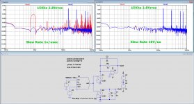
Here is the result of a simple but meaningful simulation.
In this case assuming a D/A without any slew rate restriction working at 44.1Khz
Output is 2.8mArms, translating in this case into 2.8Vrms.
One side is fed into an active I/V converter and the other side into a passive RC network enabling to compare both.
The op-amp has a parametrized slew rate.
In the plots the red line is for active and blue for passive.
I have chosen a 15Khz input frequency, that may not be the most critical, but the effect of slew rate limit is well shown.
In the left plot slew rate was set at 1V/usec, resulting in large distortion products at 900Hz and so on .
In the right plot slew rate was set at 10V/usec, where all distortion seems to be gone and both active and passive produce the same spectrum.
When translating this into a 192Khz D/A, slew rate should be some 50V/usec.
But keep in mind that the D/A in this example had no slew rate restriction, which is besides truth.
So in fact, consider the slew rate limit shown here as the max combination for: D/A + Op-Amp or D/A alone in case of a passive I/V.
Hans
Attachments
- Home
- Source & Line
- Digital Line Level
- What do you think makes NOS sound different?