Anyone here who made bass/mid/treble transformers? It's hard to get both low's and highs from the same OPT...but sumetimes there is no point in getting a wideband OPT( 2way/3way amp).
About the HF. Any ferrite used?
Wideband opt 20Hz -:- 100 KHz - no problems at all.
And yes, for optimal performance you can use ferrite for treble and permalloy/mumetal/amorphous for mid.
RDH4 by Langford-Smith is a recommended reference if you can apply some maths to the equation. I've been making some via trial-and-errors, trying every formula available and try to see where and what is really not right with each of them. Then I made a new one. So far, Pat Turner's approach is the most practical to date if you don' t mind much about cost. RDH4 is just too optimistic and ideal an approach, if you will.
By far, for me the hardest to make is the small-signal transformers; there are contradicting parameters, restrictions and limitations.
By far, for me the hardest to make is the small-signal transformers; there are contradicting parameters, restrictions and limitations.
Wire smaller than Gauge # 40 is EXPENSIVE and may be hard to find. I have a roll of # 54 but it is way too small for anything but what I bought it for. Rewinding Bulova Accutron Watch coils. # 38 which is what I use for driver transformers is good for around 22 milli amps which is about right. Simple formula for winding one is 22 X Voltage RMS you want it to put out divided by area of center leg of core. This is for 20 Hz low end.
Simple formula for winding one is 22 X Voltage RMS you want it to put out divided by area of center leg of core. This is for 20 Hz low end.
thanks, another gem of an idea picked up, will try this out....i get magnet wires smaller than #40 from these very small motors used for timing mechanisms of washing machines and electric fans...
center leg area is in squre inches, is this correct?
Hi there,
Here is a secondary arrangement which allows 4 or 8 or 16 (more exactly 4,9 and 16) with no compromise -understand: "using all the wire anyway".
Hello everybody, I've just read this thread, nice "to see" certain people together.
Bonjour Yves,
This is indeed the simplest way to have an identical frequency response on standard exits, however for the estimated 3kohms on primary you'll have more likely 3.6, 8 and 14.3 ohms in secondary. Or, as an OPT is in fact a bidirectional device, you'll have the following impedances reflected in primary (respectively, rounded) : 3350, 2975 and 3350 kohms, so the 8 ohms exit is the best guess for this arrangement, which is OK, given that most HI-FI speakers are designed for this impedance (are they?!)
Cordialement
...sorry, in my previous message it's, of course, 3350 and 2975 ohms, not kohms...
Hi Bud .... (or somebody),
Somehow I'm not able to visualize the effect of gap on nearby windings, comparing E+I versus C-core, especially regarding SE designs. Would you please elaborate a little?
Thanks,
Dorin
Hi Bud .... (or somebody),
Somehow I'm not able to visualize the effect of gap on nearby windings, comparing E+I versus C-core, especially regarding SE designs. Would you please elaborate a little?
Thanks,
Dorin
Last edited:
No, they are not !. . . given that most HI-FI speakers are designed for this impedance (are they?!)
Real loudspeaker impedance usually changes from, say, 0.8 to (more than) 5 times the value printed on the label according to the frequency

So, 10% error on the impedance ratio is "peanut"
Yves.
Somehow I'm not able to visualize the effect of gap on nearby windings, comparing E+I versus C-core, especially regarding SE designs. Would you please elaborate a little?
Were you to align two bar magnets, with a gap enforced between opposite, adjacent, poles and dropped ferrous dust between them, what would the field between them look like?
Core is a bipolar event. When there is a gap, the gap describes the polarity break.
In both cases there will be "lines of flux" that do not follow the shortest distance between the two polar end plates, These flux lines will always be curved out beyond the physical boundaries of the magnets, regardless of the gap space. A small gap has lines that extend just as far out as a large gap, but they are far more intense in field strength. This curvature will disrupt the planar field in a core window and that field disruption will affect the direct coupled field between primary and secondary.
This is not the overriding transform within the power/frequency range of the core. Above this frequency range these nonlinear fields, which are still being influenced by the physical construction of the core, will continue to cause disruption of phase in the transformation of direct coupled flux between primary and secondary.
The core swamps this gap induced effect at low frequencies. For commercial E/I core this effect is a predominate one from ~400 Hz on up. In 48% nickle ~3500 Hz , 80% nickle 10k Hz amorphous core 20 to 28 kHz.
In E/I core this effect is held to the top and bottom of the window. There are other phase destructive effects at work here though. The eventual shape of linear phase transformation in E/I core looks somewhat like a coke bottle for a push pull output and like a loaf of bread in a single ended output. I haven't investigated C core shapes, but I suspect they have a similar problem at the gap joints.
I have not found any way to eliminate the gap adjacent problem, but it can be minimized by a very useful degree. Distributed gaps that are fairly large in area, but less in stack height vs center leg width, are helpful. This ratio is also true of single gaps as stack height over square gaps have been shown to have flux that actually flows across the strip ends, rather than from plate to plate across the gap. I have also utilized "gap filler" oil from loudspeaker tech. Well, I tried to use it, but could not come up with a way to contain it, insure uniform distribution and still assemble the transformer.
The audible effect of this gap induced phase difficulty is a "sick" sound to transient structures, increasingly dysfunctional as frequency rises. Play back of a recording of a glass bell being struck will display this quite clearly.
Bud
Yves,
I was pointing out your method not blaming it!) It is, in my opinion, the best compromise for a "no compromise" approach... I know how speakers act in real world, even if we consider the impedance of speakers fixed the power source isn't, unless it's highly stabilized...
Bud,
Wouldn't a central gap on a C-core winding help a little with gap affect in a core? I'm thinking of, say, 5 mm (that will be 1/5 of an inch) gap exactly over the physical core gap, much like some of the Lundahls have.
HAs anyone some experience and practice with Alphacore C-cores? I see the M4 magnetic core very tempting...
Cheers,
Dorin
I was pointing out your method not blaming it!
) It is, in my opinion, the best compromise for a "no compromise" approach... I know how speakers act in real world, even if we consider the impedance of speakers fixed the power source isn't, unless it's highly stabilized...Bud,
Wouldn't a central gap on a C-core winding help a little with gap affect in a core? I'm thinking of, say, 5 mm (that will be 1/5 of an inch) gap exactly over the physical core gap, much like some of the Lundahls have.
HAs anyone some experience and practice with Alphacore C-cores? I see the M4 magnetic core very tempting...
Cheers,
Dorin
Hard to judge by what Lundahl does. For their amorphous core units they are faced with having to build quite a bit of distributed capacitance into the coils and also eliminate as much capacitive coupling as possible to achieve flat frequency response. Just the nature of the beast.
For an M4 core material you are going to want as much capacitive coupling as you can get, with as little distributed capacitance as possible. You can use two coils sets with a primary secondary primary winding scheme and then cross couple the primaries in an X fashion. 3mm back from the gap, for each coil should get you out of most of the seriously nonlinear field effect.
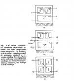
Look at the attached picture from Nathan Grossner's "Transformers for Electronic Circuits" to get a general idea. For Audio purposes you want to have the secondary driven symmetrically so you will have to imagine another primary block added to each side of the secondary, opposite the ones shown in fig C, and cross connected.
Bud
For an M4 core material you are going to want as much capacitive coupling as you can get, with as little distributed capacitance as possible. You can use two coils sets with a primary secondary primary winding scheme and then cross couple the primaries in an X fashion. 3mm back from the gap, for each coil should get you out of most of the seriously nonlinear field effect.
Look at the attached picture from Nathan Grossner's "Transformers for Electronic Circuits" to get a general idea. For Audio purposes you want to have the secondary driven symmetrically so you will have to imagine another primary block added to each side of the secondary, opposite the ones shown in fig C, and cross connected.
Bud
Attachments
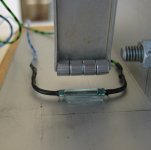
Thanks Bud, helpfull as always. I stopped a while ago compiling winding methods and I developed mine (much like fig. C in your attach.). We discuss audio transformers but the name of the game is mostly capacitive coupling, the technical version of "the beauty and the beast"
Who says transformers are boring have no idea how a capacitor works, isn't it?!
Who says transformers are boring have no idea how a capacitor works, isn't it?!
Who says transformers are boring have no idea how a capacitor works, isn't it?!
At best they still think capacitance is a lumped sum parameter. But then, finding an AC permeability chart that actually addresses permeability verses frequency, at other than 50 or 60 Hz or DC squashed, is even more exciting than counting stumps in an acre of mud.
Bud
Just saw this thread and I found it very interesting, since I have wound myself a couple of transformers. Design is from a friend of mine, who knows a lot more about output transformers than me.
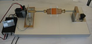
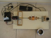
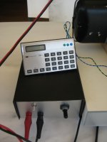
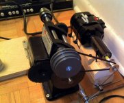
I have constructed a very simple winding machine for that purpose. It's a 24 VDC motor driving the spindle where the bobbin is mounted. The motor is driven from a PWM variable power supply to control winding speed without loosing torque. For turns count, I have implemented a very simple solution: an old calculator where I have connected a reed switch on the + button contacts. On the spindle I have mounted a series of small neodymium magnets (instead of one large - that's what I had in hand) which momentarily close the contact of the reed switch on each revolution, adding up number of turns. I also have included a footswitch, which is just an on-off switch - turning speed is varied on the PSU unit.
For the moment, I guide and stress the wire by hand (and I have learned to do so with ease, producing nice and even layers), but I plan to include Yves's "AVANCE" circuit with the needed mechanical construction for automatic advance of the wire.
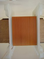
Below, you can see a couple of photos of my DIY winding machine and a sample layer while I was testing it.
I have constructed a very simple winding machine for that purpose. It's a 24 VDC motor driving the spindle where the bobbin is mounted. The motor is driven from a PWM variable power supply to control winding speed without loosing torque. For turns count, I have implemented a very simple solution: an old calculator where I have connected a reed switch on the + button contacts. On the spindle I have mounted a series of small neodymium magnets (instead of one large - that's what I had in hand) which momentarily close the contact of the reed switch on each revolution, adding up number of turns. I also have included a footswitch, which is just an on-off switch - turning speed is varied on the PSU unit.
For the moment, I guide and stress the wire by hand (and I have learned to do so with ease, producing nice and even layers), but I plan to include Yves's "AVANCE" circuit with the needed mechanical construction for automatic advance of the wire.
Below, you can see a couple of photos of my DIY winding machine and a sample layer while I was testing it.
Attachments
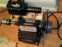
This is my tertiary winding machine (a Nittoku as primary), mostly for small tasks, winding wire reels and never ending tests. For a DIY enthusiast, spending about $200 for a coil winder project it's almost a minimum. Well, that's the price for this little chinese machine bought on eBay (Coil audio Output transformer motor winding machine 2 | eBay). Having one and testing it will turn out that, as it is, it's pretty useless; the original sewing machine motor it's a joke; it has 10,000 RPM (no bearings) and it's very weak - anyway, the overall speed it's far too fast. I have (gladly) replaced the original motor with a junk-recovered ugly beast having lower RPMs and a lot of power. I had to adapt the rectifier bridge and the power MOSFET transistor inside and I've adapted the signal from HALL counting sensors to a stepper (via a Vexta driver and lately to a Mdrive17 from IMS); now it's meaning business...
No, I have no schematic for the original winding machine, I'll be thankful to anyone providing me one, as I'm still thinking several scenarios with this setup.


No, I have no schematic for the original winding machine, I'll be thankful to anyone providing me one, as I'm still thinking several scenarios with this setup.
Last edited:
- Status
- This old topic is closed. If you want to reopen this topic, contact a moderator using the "Report Post" button.
- Home
- Amplifiers
- Tubes / Valves
- Who makes their own OPT around here?