When we talk topology its most usual we refer to electrical slopes if we refer with dB. Like we see a crossover with one coil in series to the woofer plus a capacitor in series & a coil in parallel to the tweeter and we describe it as 6dB/12dB. That way we can all picture it in our minds the same for number of parts and what connections. When we analyze curves we should talk actual combined electrical + acoustical output rates of slopes.
Xsim to avoid confusion, says order instead of dB in its CircuitBlocks menu. Like HighPass2ndOrder etc.
Xsim to avoid confusion, says order instead of dB in its CircuitBlocks menu. Like HighPass2ndOrder etc.
When we talk topology its most usual we refer to electrical slopes if we refer with dB. Like we see a crossover with one coil in series to the woofer plus a capacitor in series & a coil in parallel to the tweeter and we describe it as 6dB/12dB. That way we can all picture it in our minds the same for number of parts and what connections. When we analyze curves we should talk actual combined electrical + acoustical output rates of slopes.
Xsim to avoid confusion, says order instead of dB in its CircuitBlocks menu. Like HighPass2ndOrder etc.
What about phase shift? Does an acoustical slope of 12db have 180 degrees phase shift even if the electrical slope is 6db?
Filtering is filtering whether electrical or acoustical (or, as in reality, both). In minimum phase systems (almost all passive crossover filters and single drivers), the overall slope will determine the ultimate phase shift. Along with the absolute delay due to the finite speed of sound and distance from the driver to the microphone, of course. And the crossover "Q" between drivers will affect the relative phase shift at the crossover point as well, but the 90 degree per "order" will still be a good estimate. Of course, for speaker design, DON'T ESTIMATE --- MEASURE.
There are ways to do "all-pass" sections in a crossover filter to make it non-minimum phase -- to have MORE phase shift. And there are FIR type DSP filters which can have the phase response be almost arbitrary (though a fixed delay is always inherently added to get there, so the phase response spoken of is always the phase shift after the added overall non-varying delay).
There are ways to do "all-pass" sections in a crossover filter to make it non-minimum phase -- to have MORE phase shift. And there are FIR type DSP filters which can have the phase response be almost arbitrary (though a fixed delay is always inherently added to get there, so the phase response spoken of is always the phase shift after the added overall non-varying delay).
Hello forum!
I am in the middle of my first passive crossover design and would like to ask for some advice. My system i a 3-way speaker with a 15" midbas driver, 2" CD on a horn for midrange (Renkus Heinz 3301) and a 1" CD on a horn (Faital HF108). The system is somewhat inspired by Klipsch Cornwall or so.
The system will be biamped, a class D amp for the woofer and another SET amp for mid and tweeter. So my task is to design a passive crossover network for the two horns.
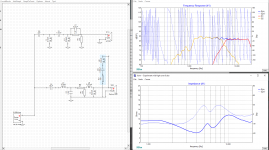
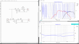
So now I have assembled the cabinets, put all drivers on and made measurements of each driver, both frequency responses and impedance. From REW I managed to generate .frd and .zma. Then I did my best to model a network in Xsim somewhat inspired by Klipsch or JBL networks. In attachments there are pictures of the two simulations, in one case I aimed for the flat frequency response while keeping "not too bad" impedance, while the other represents a fairly good impedance with "not too bad" frequency response. Unfortunately I struggle to achieve good results for both curves in the same time. I assume it is because the two horns have different depth and the drivers are some 5" out of phase between each other.
I would like to ask some opinions and advice maybe which way to go and whether the graphs look reasonable to do some prototyping.
Thanks.
I am in the middle of my first passive crossover design and would like to ask for some advice. My system i a 3-way speaker with a 15" midbas driver, 2" CD on a horn for midrange (Renkus Heinz 3301) and a 1" CD on a horn (Faital HF108). The system is somewhat inspired by Klipsch Cornwall or so.
The system will be biamped, a class D amp for the woofer and another SET amp for mid and tweeter. So my task is to design a passive crossover network for the two horns.
So now I have assembled the cabinets, put all drivers on and made measurements of each driver, both frequency responses and impedance. From REW I managed to generate .frd and .zma. Then I did my best to model a network in Xsim somewhat inspired by Klipsch or JBL networks. In attachments there are pictures of the two simulations, in one case I aimed for the flat frequency response while keeping "not too bad" impedance, while the other represents a fairly good impedance with "not too bad" frequency response. Unfortunately I struggle to achieve good results for both curves in the same time. I assume it is because the two horns have different depth and the drivers are some 5" out of phase between each other.
I would like to ask some opinions and advice maybe which way to go and whether the graphs look reasonable to do some prototyping.
Thanks.
Attachments
I think I managed, please find attached. I had to do some double zipping ")
Generally I find the horns not so easy to work with as a first network design, but it is an interesting challenge. The main issue I believe is the phase integration because of the time delay between the drivers due to horn depth.
Any advice would be very appreciated.
Generally I find the horns not so easy to work with as a first network design, but it is an interesting challenge. The main issue I believe is the phase integration because of the time delay between the drivers due to horn depth.
Any advice would be very appreciated.
Attachments
Okay, then it I assume it did not work with archiving.
In this case I attach archives with .zma and .frd as well as a picture of the system.
The delay for the tweeter (HF108) is 5.5 inches.
The delay for the midrange (3301) is 9.5 inches.
Hope this is sufficient.
Meanwhile I will try to upload the .dxo somewhere and share a link.
In this case I attach archives with .zma and .frd as well as a picture of the system.
The delay for the tweeter (HF108) is 5.5 inches.
The delay for the midrange (3301) is 9.5 inches.
Hope this is sufficient.
Meanwhile I will try to upload the .dxo somewhere and share a link.
Attachments
I'll take a look at it and see if I can add anything to improve the circuit topology.
edit: I suggest you first improve on the phase data of each driver by incorporating the minimum phase and then try your crossover again. I tried to do that myself but excel spreadsheet response modeler would not load it. I can feed the XSim with it and then export it to RM, which then again gets smoothed too much once in XSim again.
edit: I suggest you first improve on the phase data of each driver by incorporating the minimum phase and then try your crossover again. I tried to do that myself but excel spreadsheet response modeler would not load it. I can feed the XSim with it and then export it to RM, which then again gets smoothed too much once in XSim again.
Last edited:
Lojzek, not sure I understood you correct, but I guess you mean to "derive" in Xsim frd and zma phase sources, right?
I have read some info how to do that as well as how to measure and define the speaker acoustic center precisely. So I will try to do a new measurement now to get it hopefully more precise. As well as to do the "derive" thing.
Question: when I measure tweeters can I connect it directly to an amplifier and just do the measurement, say from 500Hz or is it okay to have a capacitor?
You gotta let a program (XSim, FRD Response Blender, Response Modeler) derive the minimum phase of the raw unit before you start designing the crossover. I have used Clio mls measuring signal only without any problem, so I suppose you would not have any with REW as well if you were careful with voltage setting of the amplifier. Perhaps best to ask REW users.
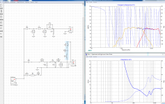
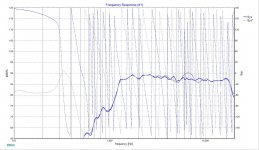
So I made new measurements, found the precise acoustic center and derived phase sources. Then I tried playing with crossover a bit. Here is the result:
Calibrated 1 1.dxo - Google Drive
How does it look now?
Calibrated 1 1.dxo - Google Drive
How does it look now?
Lojzek, I really appreciate your help.
I followed your advice and did as you recommended. To compensate for the impedance peak I also added an LCR loop across the amp out. It does not affect the frequency response, but whether it is a good idea to have it in reality is a question mark. What do you think?
Here is the latest simulation:
Calibrated 1 2.dxo - Google Drive
I want to share one observation. When I measured a physical distance between driver diagrams it was about 4 inches. When I measured it however, it showed 5.12 inches instead, which is interesting. This is why mainly the crossover changed somewhat.
Impedance flattening circuits can be useful with amps of high output resistance but you would need to measure the whole speaker, woofer included. Simulation is just a step to figure out ball park values, this should be confirmed with actual parts and then modified if necessary, to be on the safe side. Latest xo version appears ok.
- Home
- Design & Build
- Software Tools
- XSim free crossover designer