I bought Yamaha A-500 with defect for 30 bucks .. I replaced burned output trans, it working, but speaker protection circuit does not switch output relay.. I am not sure, if is there delay only , or is there some voltage detection yet ... Any advice? I have to set up bias(don´t know exact value) and offset (don´t know where)
Here is schematic...
Here is schematic...
Attachments


yes ..the obvious ...
----check on the emitter resistors center versus ground to see if there is and DC present ..well it shouldn't...at least no more than 50 mv.If more relay will not click
----Search for other parts that might be open or shorted driver area fusible resistors on collector of drivers and so on
----Check for all voltage present
----Verify voltage present on the relay versus ground it should be always there ( protection circuit controls ground for the relay )
----E mail me for schematic
Kind regards
Sakis
relay click, if is volume set to zero .. when I turn volume up(with sine source) relay opens .. signal is OK before relay
Might be a hard issue to trace
Original circuit has a few complexities not always easy to understand
--check if the pre is injecting any DC to the input of the main amplifier
--make tests again excluding tone control circuit there might be something wrong there that eventually effect the main amplifier since tone control is nested in the feedback chain
---Replace electrolytics around protection area check or replace worn parts ...
Use dim bulb , dummy load and scope to estimate signal before the relay in order to discriminate if the amplifier has a real problem or protection circuit is screwing around with you
Kind regards
Sakis
The relay protect circuit has some caps that dry up and cause this failure, replace all the small electrolytics and be done with it.
I had a big professional amplifier with a bad solder joint on one of these caps, it would shut off with any signal when you turned up the volume. Glued the cap down to the board and re-soldered it, fixed.
Your caps are just dried up.
Small electrolytic caps are like roaches, you got to get 'em all!
I had a big professional amplifier with a bad solder joint on one of these caps, it would shut off with any signal when you turned up the volume. Glued the cap down to the board and re-soldered it, fixed.
Your caps are just dried up.
Small electrolytic caps are like roaches, you got to get 'em all!
I've experienced the same djk says, but on consumer Yamaha amps, much like this one. Works at no volume, turn it up a bit and the relay clicks off. New lytics around the relay fixed the issue. Apparently fairly common on Yamaha.
relay click, if is volume set to zero .. when I turn volume up(with sine source) relay opens .. signal is OK before relay
Check Tr119,Tr121, R235 & Tr120, Tr122, R236.


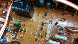
You say "burned part of PCB". Is that just meaning where there is a problem or where the PCB is literally "burnt" as in black and maybe conductive?
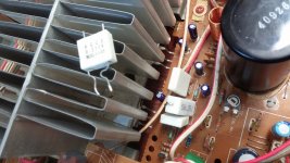
Guys, thank you so much for cooperation, problem is solved... There was three problems, first was burned output trans, second burned part PCB, and last was that emitters resistors(there are 0,22R) was burned on both sides... I thought, that output is running but 🙂
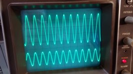
So , my last question, does anybody know bias value? I already set 130mA
Some pictures sine at 100Khz and square at 10Khz
So , my last question, does anybody know bias value? I already set 130mA
Some pictures sine at 100Khz and square at 10Khz
Attachments

Last edited:
Yamaha A-500 Manual - Stereo Integrated Amplifier - HiFi Engine
The service manual specifies 15mV measured across TP1-2. & TP3-4. That amounts to 0.015/0.22 = ~70mA.
The service manual specifies 15mV measured across TP1-2. & TP3-4. That amounts to 0.015/0.22 = ~70mA.
TP1/2; TP3/4 are points of R241/242 0,22Ω resistor. I=U/R = 0,068A
An externally hosted image should be here but it was not working when we last tested it.
- Home
- Amplifiers
- Solid State
- Yamaha A500 repair