Hello, first off I want to say I've been visiting this site many times in the past to get help thru many a repair and the members here are an awesome source of info and I want to thank everyone. Today I need help that I can't seem to find anywhere even tho it seems like a fairly common problem for the Yamaha RX series amplifiers. I have a RX-V1500 that turns off 3 seconds after I turn it on and after putting it in diagnostic mode I get the DC 000 G diag message on screen. So I checked for DC at my speaker terminal and I have 18-20 volts at ALL the terminals. This unit worked perfectly when I turned it off but later that day I went to turn it on and it turn itself of right away. Now I love the sound of this unit and don't require HDMI as I don't run video thru it. Please if any one can point me in a direction I'd be eternally grateful.
Ps I'm in no way a professional electronics technician, I am an auto mechanic by trade lol.
Ps I'm in no way a professional electronics technician, I am an auto mechanic by trade lol.
4 x speaker protection relays suggest the above is unlikely - I'm assuming (dangerous) that you checked ALL 7 x speaker outputs....So I checked for DC at my speaker terminal and I have 18-20 volts at ALL the terminals.
Do you hear the speaker relays engage?
The good news is that if the amp remains powered-up whilst in DIAG mode, you can search for the missing/errant voltage(s).
Scroll through the DIAG list for more clues (if there are any...).
Good Luck!
Yes I checked all 7 outputs and they all have -18 to -21 volts. If I try to turn it on normally it just turns off after 3 seconds, but in diag mode it stays on and all relays engage yes. Where would you suggest looking for stray voltage? I was hoping to see a burnt part, smell something fishy, or see full rail voltage on a single output but having only 1/3 rail voltage on all outputs has got me stumped.
Yep, agree DC 000 means the amp is in protection because of an unexpected/missing voltage. A voltage of 000% was "detected" so suggest you check the power supplies/voltage regulators, highly likely you've got a failed regulator, a relatively easy problem to troubleshoot. The RX-V's and other HT gear are generally cost prohibitive to repair, you might be lucky.4 x speaker protection relays suggest the above is unlikely
having only 1/3 rail voltage on all outputs has got me stumped.
Look for blown fuses first. Some could even be soldered on boards.
I can't get the images you uploaded to load, I really appreciate your help and giving clear instructions on what my next process should be.
I found the power (3)PCB but can't seem to locate any of the suggested parts, again I really appreciate your help. I just really enjoy the sound from this amp and because HDMI isn't important to me I think I would need to spend 1500$ to get anything close to the sound quality in today's market. Thank you in advance for all your help
MBZ, I checked all the pins on all the transistors on the power (3) PCB and I'm getting between 5-19 volts on most of them (couldn't identify which parts you were referring to as the images didn't load) but the one thing I noticed was they get hot very quickly, maybe this is normal as they are not mounted to the heat sink during the time I was making this measurements.
Ps I'm new to posting on a forum and apologize if I'm not replying the correct way. Thank you again for all your help.
This is a hugely complex piece of equipment and I would suggest that as much evidence be gathered in the form of voltage measurements before disturbing anything.
I would begin by looking at why you have such a high DC voltage on the actual speaker terminals because that to me suggests a measurement error for the following reasons:
1/ All the power amps can't be bad at once.
2/ An offset fault on one should disconnect them all (speaker relays).
3/ It is remotely conceivable that multiple rail failures could both give a DC offset and cause the speaker relays to remain engaged.
You say you have 18 volts on ALL terminals by which I assume you mean the negative terminals as well.
First thing has to be to recheck the initial measurements by using a suitable power supply ground as a reference.
If you have 18 volt on the speaker ground as well as the speaker + terminals then you have some physical issue of open connections (such as the unit being dropped)
If just 18 volt on just the + speaker outputs then begin by checking all the rails to the power amps and seeing why they are all generating an offset.
I've double and triple checked and when I put it into diagnostic mode I have 18-20 volts on every single speaker terminal.
MBZ, I checked all the pins on all the transistors on the power (3) PCB and I'm getting between 5-19 volts on most of them (couldn't identify which parts you were referring to as the images didn't load) but the one thing I noticed was they get hot very quickly, maybe this is normal as they are not mounted to the heat sink during the time I was making this measurements.
 If you run the regulators without the heatsink, your amplifier may be beyond economical repair: i.e. it'll be considerably less expensive to purchase a new amp.
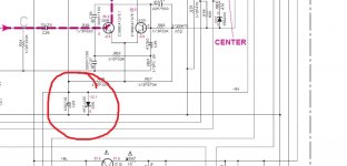
 Based upon your supplied information and extrapolating (I'm assuming that there is NO DC voltage at the speaker outputs until the relays engage in DIAG mode), check the voltage across D25 on the POWER1 PCB. It should be -12V DC.


N.B. The information you receive is based on the information you supply. If you supply erroneous information, the amplifier will spontaneously combust!
Also, if you accidentally (or deliberately) create sparks whilst taking live measurements, you will have to purchase a new amplifier.
Please exercise extreme caution. And don't forget, the mains voltage for your country is exposed on the POWER5 PCB.
Good Luck!
Thanks for the reply Moily I really appreciate your help. The anno needs to be in diagnostic mode to actually have the DC on my speaker terminals and I'm measuring by putting my test leads on the terminals themselves -to- +to+ so testing one speaker output at a time in getting 18-20 volts on all terminals. If I check it with the neg of my DVM to chassis ground I only get voltage on the + terminals. 18v on my fronts A&B and 20.6 on all surround speakers. Again thank you for waking me thru this I really appreciate all the help I've received thus far.
So...
Pick one channel and work with that seeing why there is 18 volts offset.
The power amp sections are classic text book design although split over two pages in the manual. The input is AC coupled and so the amp works in total isolation. If the supplies are correct then the offset should be zero.
One point... your measured 18 volts should be rechecked before the relay because if the relay is actually open then you may be reading noting more than stray pickup. You can actually check for that by simply tagging a 1k resistor across the speaker output. The resistor would kill any stray voltage.
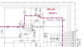
So try and see why this amplifier (Front Left) has 18 volts offset and see where some measurements get you
Pick one channel and work with that seeing why there is 18 volts offset.
The power amp sections are classic text book design although split over two pages in the manual. The input is AC coupled and so the amp works in total isolation. If the supplies are correct then the offset should be zero.
One point... your measured 18 volts should be rechecked before the relay because if the relay is actually open then you may be reading noting more than stray pickup. You can actually check for that by simply tagging a 1k resistor across the speaker output. The resistor would kill any stray voltage.
So try and see why this amplifier (Front Left) has 18 volts offset and see where some measurements get you
Attachments


Mooly, thanks again for replying so quickly. The further I dig into this thing the more I'm thinking I'm over I'm in way over my head lol. It's definitely pushing DC out of the speakers because when I turn it on in diag mode it pushes my speakers(all 7 speakers) out to their limits. I'm just so stumped to why all 7 channels would do this at the exact same time and it was working perfectly when I shut it off earlier that day. I will try to make those measurements you pointed out tho, I'm just trying to identify which channel is where inside the unit.
I feel like I'm a complete idiot trying to figure this thing out, I am sorry to ask you kind souls trying to help me out as I really feel like I have no clue as to what I'm doing. I'm gonna take a chance and guess that the front channels are the PCB directly behind the power 3 board (the board With 7 transistors and mounted up top about 4 inches behind the front panel). I know this is at least part of the amplifier section but not certain if it's front of another channel. Thanks again to all of you helpful people and bless your soul for helping someone who's feeling dumb.
I feel like I'm a complete idiot trying to figure this thing out, I am sorry to ask you kind souls trying to help me out as I really feel like I have no clue as to what I'm doing. I'm gonna take a chance and guess that the front channels are the PCB directly behind the power 3 board (the board With 7 transistors and mounted up top about 4 inches behind the front panel). I know this is at least part of the amplifier section but not certain if it's front of another channel. Thanks again to all of you helpful people and bless your soul for helping someone who's feeling dumb.
Last edited by a moderator:
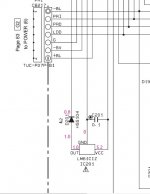
The way to fix this is to work with something definite and that (to me) has to be the fact that each power amplifier is self contained. Each is complete in itself and should have no DC on the output as long as:
1/ The supplies are correct.
2/ There isn't a fault within that part of the circuit (unlikely all of them have the same fault).
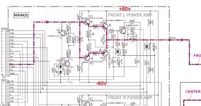
So four measurements should get you some kind of answer as to what is going on.
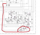
There should be +60 volts and - 60 volts present on the output transistors.
There should also be + 60 volts on the front end circuitry.
Common to all, and so first to check is this little auxiliary -12 volt rail.
If that is missing then trace the supply back to Q21 and R37 see if the -60 volts input is present there.
1/ The supplies are correct.
2/ There isn't a fault within that part of the circuit (unlikely all of them have the same fault).
So four measurements should get you some kind of answer as to what is going on.
There should be +60 volts and - 60 volts present on the output transistors.
There should also be + 60 volts on the front end circuitry.
Common to all, and so first to check is this little auxiliary -12 volt rail.
If that is missing then trace the supply back to Q21 and R37 see if the -60 volts input is present there.
Attachments
Hello Mooly, Hmmm. Look what I found while doing those measurements, I found this little resistor that I'm guessing may be slightly out of spec lol 🤪. Now I need to actually pull this entire unit apart to replace it, I know why I became an auto mechanic lol. Anyways what should I check before replacing and powering up the unit as I don't want to just blow the new part. Thanks again for helping me thru this, I probably would have given up after I took the cover off and seen how complex these amps have become if it wasn't for all the help from you and the rest of the diyaudio members. Anyways any other information or advice you can give at this point will be greatly appreciated. Thank you so much,
Attachments
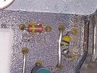
Mooly, it's the MAIN (2)PCB and it's the C201 resistor. You are the best, I appreciate your help more then I can ever express, thank you.
Ps. Yes it was working perfectly when I turned it off and later that day I went to turn it on and it turned itself off 3 seconds later.
Ps. Yes it was working perfectly when I turned it off and later that day I went to turn it on and it turned itself off 3 seconds later.
Last edited:
C201 would be a cap and in fact the part does look like a tubular ceramic cap. The LM61CIZ is a temperature sensor IC. Unless you have cracked the resistor somehow in working on it... I would suggest its always been like that. The cap is for decoupling and it would probably work OK without it.
I wouldn't worry to much at this stage over that part... do the fault finding as I suggested. There is a fair chance that auxiliary rail I mentioned is missing.
I wouldn't worry to much at this stage over that part... do the fault finding as I suggested. There is a fair chance that auxiliary rail I mentioned is missing.
Attachments
- Status
- This old topic is closed. If you want to reopen this topic, contact a moderator using the "Report Post" button.
- Home
- Amplifiers
- Solid State
- Yamaha RX-V1500 help please