Do you mean this?Hi tiefbassuebertr,
No wonder you get confused by explanations like that and start talking about opposite phases, negative group delays and diagonal harmonic modulators.
It´s mainly about voltages. Imagine a balanced resistor bridge, where in a relevant circuit R1/R2=R3/R4. For less power losses, two resistors are replaced with an inductor and a capacitor, giving the same impedance ratio, however, not making the examination easier: 1/C1/R2=R3/L4. The error cancellation relies on that balance (not ß).
Attachments
"Can you give my a "tutorial" how to order the schematics.
And how much will it cost. "
Im pretty sure I just gave you the MX10000 (pc5002M) schematics in my last post
Craig, the PC-5002M schematics is not equivalent to the MX-10000.
The Hifi equivalent of the PC-5002M is the 101M monster amplifier.
Hi tiefbassuebertr,
No wonder you get confused by explanations like that and start talking about opposite phases, negative group delays and diagonal harmonic modulators.
It´s mainly about voltages. Imagine a balanced resistor bridge, where in a relevant circuit R1/R2=R3/R4. For less power losses, two resistors are replaced with an inductor and a capacitor, giving the same impedance ratio, however, not making the examination easier: 1/C1/R2=R3/L4. The error cancellation relies on that balance (not ß).
We have many key words to differentiate between the exact interpretation and the colloquial interpretation. The term "feedforward correction" ("feed forward correction") is probably such a term and is - so I guess - therefore used as colloquially term for the description of error correction (distortion cancellation) procedures in the "Current Dumping" principle and cannot be used as exact interpretation.
In this case here two weblinks, one in English and one in German
AES E-Library: Feedforward Error Correction in Power Amplifiers (I have the orig. article, but it is a pdf file of 30 Mbit through scanned originale dokument)
Fehlerkorrektur (Regelungstechnik) – Wikipedia
Because I have make the interpretation of "Feedforward" exact (my english is very bad regarded colloquial interpretations), I came to the result of #53 on page 6 of this thread
The original article of "Feedforward Error Correction in Power Amplifiers" you can download by http://quad405.com/jaes.pdf
Sandman's Distortion Reduction by error add-on and Error Feedforward - "Other Error Correction Modes" from the book
“High perfomance audio power amplifiers for music performance and reproduction” - also of interest in this case:
Sandman's Distortion Reduction by error add-on and Error Feedforward - "Other Error Correction Modes" from the book
“High perfomance audio power amplifiers for music performance and reproduction” - also of interest in this case:
Attachments
In most cases I must pay for download patent pdf documents. Here a weblink for free download without registered:
Error!
to get this patent, please fill in exactly the follow:
us4,160,216
An additional weblink for free download without registered:
PAT2PDF - Free PDF copies of patents: Download and print!
The good known patentarchive
Apparatus for eliminating on-off transitional gain variations in class AB, B and C active element amplifiers - US Patent 4160216 Abstract
is only for registered users.
Maybe this is for free:
Patent Searching and Inventing Resources
Cheers!
low voltage OPA's for creating a HCA topology as small audio amp
If I had an audio power amp (or OP amp) IC for small supply voltages with high quiescent current, it could be easy to create a small HCA-amp with help of the LM3886 about
LM3886 - High-Performance 68W Audio Power Amplifier with Mute
Who knows such types?
If I had an audio power amp (or OP amp) IC for small supply voltages with high quiescent current, it could be easy to create a small HCA-amp with help of the LM3886 about
LM3886 - High-Performance 68W Audio Power Amplifier with Mute
Who knows such types?
Hi,
The problem is that the class A "bridge" buffer must sink all the current from the AB Powerstand AND provide the Error Correction.
This why normally the ECC Amp runs in parallel with the main Amp, as the ECC Amp only needs a modest amount of power into the actual load resistive summing can be used. Open loop output stages can be made to have < 0.3% THD at 20KHz and near full power.
So taking something like the LM3886, we need 0.3% or less of 68W/4Ohm. I suspect a Single Ended Mosfet buffer running from a lowish supply after (say) a OPA2604 may do the trick for running the direct and ECC Amp in parallel.
Ciao T
If I had an audio power amp (or OP amp) IC for small supply voltages with high quiescent current, it could be easy to create a small HCA-amp with help of the LM3886 about
LM3886 - High-Performance 68W Audio Power Amplifier with Mute
The problem is that the class A "bridge" buffer must sink all the current from the AB Powerstand AND provide the Error Correction.
This why normally the ECC Amp runs in parallel with the main Amp, as the ECC Amp only needs a modest amount of power into the actual load resistive summing can be used. Open loop output stages can be made to have < 0.3% THD at 20KHz and near full power.
So taking something like the LM3886, we need 0.3% or less of 68W/4Ohm. I suspect a Single Ended Mosfet buffer running from a lowish supply after (say) a OPA2604 may do the trick for running the direct and ECC Amp in parallel.
Ciao T
there is a second thread by same topic:
http://www.diyaudio.com/forums/solid-state/142233-yamaha-hca-circuit.html
here is to find an IC with HCA topology.
http://www.diyaudio.com/forums/solid-state/142233-yamaha-hca-circuit.html
here is to find an IC with HCA topology.
These problems are much easier to solve when you look at them in quadrature.
You merely need two feedback loops at 90 degree angles of relative activity.
First loop holds firm control over push pull currents in a differential mode.
First one is watching amplified output voltage and making sure its linear.
For reason of this intended result, we could say it controls Voltage.
This loop we all know, nothing new to be seen here.
Second loop holds firm control over push pull currents in the common mode.
Second is watching amplifier current, making sure it never his zero, nor runs
away, and shaping the common mode to a "sum of two square laws" curve.
This one is where we break from tradition. Our bias spreader is active over
the full spectrum of music, rather than being shunted by a low pass cap.
Two loops at 90deg angles: one controls voltage, other controls current...
Last edited:
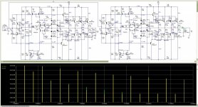
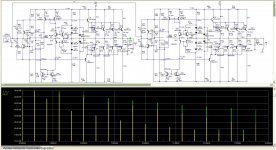
Another play on my simulator proved the following scenario. The difference between the two schemes is the lack of a capacitor C5 in the second scheme in which the second scheme of non-switching/Yamaha's Hyperbolic Conversion Amplification / switches to class B. Initial current of both schemes is identical.
It is clear that options class B / pic 2 /, the values of the odd harmonics are lower.
In / pic 1 / shows what is gained from Non-switching options. Almost nothing.
My question is why yamaha have pushed and complicated scheme, further complicated innards, it is worse / according to the simulator /, is it just a marketing strategy / although it is nowhere specified that the amplifier is Non-switching / the whole thing or just the simulator is not allowed to show the real things that really happen?
Whether these "crossover distortion", which is avoided by Non-switching options are included in the harmonic spectrum?
Attachments
-30dB nonlinearities can't be, not even in simulation ...
The Yamaha MX-10000 was the only amp, where true HCA was implemented, the other so called HCA amps (MX-1000, 2000 etc.) were more or less engineered by marketing department ...
On the MX-10000 Yamaha claimed Class A operation up to 1200W (1Ohm), which is essentially true, if one ignores the minor but still existing impact of the slave Class (A)B amp on overall linearity.
With the MX-10000 there come THD plots in the user manual, which show, that the amp does something like 0.0002% at 6 Ohms and half power at 20kHz. True measured performance !
This is a very good linearity, which probably was never reached by any other commercial amplifier, except perhaps Halcro.
Don't also forget, that this was 1987 and IMO the sonic result justified any penny/effort, because this amplifier not only measures good, it also sounds amazingly clean.
Trying to build this amp in DIY is IMO a failure by definition, because schematics topology is one thing, but physical layout and related tweeking another very crucial point, which can't be covered in an affordable way by any one-man DIY effort.
Hi Jon Lord, It's -30dB, but the 1khz level is +35db. The distortions are -70dB second harmonic. The HCA works by simulator, but the result is worse that class B on 50mA current. Why?
When I set current on 200mA the HCA is the best, but this is a lot of heat.
After you tell me about MX-10000, I found the service manual and saw the circuit. Yes, this yamaha is very good build and very powerful. This is the true amplifier. I saw the HCA circuit of MX-10000 and I tested on my simulator, but It doesn't work!!!
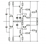
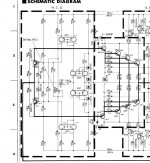
Where did you find MX-10000 service manual ?After you tell me about MX-10000, I found the service manual and saw the circuit.
The original MX-10000 HCA circuit look like this.Yes, this yamaha is very good build and very powerful. This is the true amplifier. I saw the HCA circuit of MX-10000 and I tested on my simulator, but It doesn't work!!!
And don't forget that MX-10000 use a real feed forward error correction.
Attachments
Where did you find MX-10000 service manual ?
Download the Yamaha MX-10000 service manual for free - Hifi Manuals
This is pure class AB with switching. What are you think about the circuit? Is it right?
I don't have good spice model of power mosfet transistors but I think is not critical for simulation.
Attachments
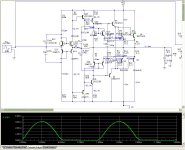
This is the HCA including component values...
Have not yet had the time to start simulation...
seem like it could be a good starting point for a power-buffer for a non global feedback amplifier-circuit
This is my test circuit in my upstairs post, if you can't set current to 200mA is worse from pure class AB circuit with 70mA current.
- Home
- Amplifiers
- Solid State
- Yamaha's Hyperbolic Conversion Amplification (HCA) Circuit