Some first measurements then. The membrane is not vertically suspended, it just the friction of the foam that holds it up.
Membrane is 3M's 74 film with the cut 7 µm aluminium on one side and a uncut 7 µm aluminium on the other side.
This is to keep the corrugation.
1/24 octave smoothing.
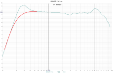
SPL 1W at 1 m:

So it's 75 dB at 1W at 1 meter with a 4 ohm resistor in series.
With all eleven elements it should be 85 dB, but with all elements pushing the same air and that this is a line source, I reckon that the sensitivity will be around 90 dB for the complete loudspeaker.
And if I find a way to keep the corrugation without the extra aluminium layer there should be yet another couple of dBs .
The Helmoltz's resonance is clearly visible and is around the calculated frequencies.
The Q value is rather low, but I guess the corrugatad membrane smooths it out.
One thing that is very obvious is that I don't need a separate tweeter membrane!
Distortion at 1W 1m:

Nothing much to do here!
Note that the distortion levels are below the noise floor.
I'm not to worried for the SPL around 400 Hz, this is how it measures at 0.4m:

Then I waved the microphone a little (MMM) at 1 m:

MMM at 0.4 m:

Membrane is 3M's 74 film with the cut 7 µm aluminium on one side and a uncut 7 µm aluminium on the other side.
This is to keep the corrugation.
1/24 octave smoothing.
SPL 1W at 1 m:
So it's 75 dB at 1W at 1 meter with a 4 ohm resistor in series.
With all eleven elements it should be 85 dB, but with all elements pushing the same air and that this is a line source, I reckon that the sensitivity will be around 90 dB for the complete loudspeaker.
And if I find a way to keep the corrugation without the extra aluminium layer there should be yet another couple of dBs .
The Helmoltz's resonance is clearly visible and is around the calculated frequencies.
The Q value is rather low, but I guess the corrugatad membrane smooths it out.
One thing that is very obvious is that I don't need a separate tweeter membrane!
Distortion at 1W 1m:
Nothing much to do here!
Note that the distortion levels are below the noise floor.
I'm not to worried for the SPL around 400 Hz, this is how it measures at 0.4m:
Then I waved the microphone a little (MMM) at 1 m:
MMM at 0.4 m:
Amazing!
If I understood correctly then that speaker uses 5mm wide and 3mm tall magnets, with 5mm gaps in between the magnets? And a 4mm gap between the magnets?

If the Helmoltz's resonance is uniform on and off axis then it should be easy to handle.
Are you still planning to cross steeply at 400-500 hz? Assuming that the driver is 220 cm x 3.5 cm with a 10 cm baffle width then 4 mm gap might be overkill considering the max SPL levels for +- 0.1 - 0.4 mm (unless you want to play really loud of course )
)
+- 0.1mm will give you 101 dB @ 400 hz

+- 0.4mm: 113 dB @ 400 hz

If I understood correctly then that speaker uses 5mm wide and 3mm tall magnets, with 5mm gaps in between the magnets? And a 4mm gap between the magnets?
If the Helmoltz's resonance is uniform on and off axis then it should be easy to handle.
Are you still planning to cross steeply at 400-500 hz? Assuming that the driver is 220 cm x 3.5 cm with a 10 cm baffle width then 4 mm gap might be overkill considering the max SPL levels for +- 0.1 - 0.4 mm (unless you want to play really loud of course
)+- 0.1mm will give you 101 dB @ 400 hz
+- 0.4mm: 113 dB @ 400 hz
About Helmholtz-resonance: I think, the lobing effect can cause rising frequency response. If the supernearfield (1cm) measure is possible, it can confirm or refute the lobing-theory. The Helmholtz-resonance and lambda/4 acoustical impedance transformation can make similar effect. I don't know, which effect dominates.
Thank you for a lot of info from your experiment!
Thank you for a lot of info from your experiment!
@OllBoll:
Yes, you got the dimensions right.
I will now make a new design with only one membrane but still 135 mm wide baffle.
@neodymium:
Good idea, I will measure the extreme nearfield tomorrow.
After that, I will straighten the membrane to get rid of the corrugation and measure anew.
Yes, you got the dimensions right.
I will now make a new design with only one membrane but still 135 mm wide baffle.
@neodymium:
Good idea, I will measure the extreme nearfield tomorrow.
After that, I will straighten the membrane to get rid of the corrugation and measure anew.
I think the high orders bump from 200-400 hz is just because there is a large peak there. I think if you added a notch filter such that the slope is smooth then the bump in distortion will go away. Or at least until you bump the power & SPL but then the distortion will increase everywhere and not just in the 200-400 hz region.
Attachments
Very interest! The hump is smaller, but the 10-11kHz peak still same. The high frequency beaming and the Helmholtz-resonance (or/and transmission-like effect of magnet rows) are synergistic. Another surprise for me is the slope at high side.
Amazing smooth midrange! I think, it should be a good headphone too.
Amazing smooth midrange! I think, it should be a good headphone too.
I will keep the 4 mm gap between the magnets as that distance simulated the best.If I understood correctly then that speaker uses 5mm wide and 3mm tall magnets, with 5mm gaps in between the magnets? And a 4mm gap between the magnets?
Are you still planning to cross steeply at 400-500 hz? Assuming that the driver is 220 cm x 3.5 cm with a 10 cm baffle width then 4 mm gap might be overkill considering the max SPL levels for +- 0.1 - 0.4 mm (unless you want to play really loud of course
The corrugation eats up 1 mm of the gap and I want at least 0.5 mm clearance, together with the Xmax there's still a millimeter or so left.
So I thought I'll try some 0.3 mm felt on the magnets.
I have some ideas when it comes to the front panel' surface. Stay tuned.Very interest! The hump is smaller, but the 10-11kHz peak still same. The high frequency beaming and the Helmholtz-resonance (or/and transmission-like effect of magnet rows) are synergistic. Another surprise for me is the slope at high side.
Yes, that might be in the future.Amazing smooth midrange! I think, it should be a good headphone too.
Something like this then:

The big wave guides on the sides can of course have a better acoustic shape.
The wider steel plate makes room for two columns of fastening for each side.
I hope then that the free 64 mm membrane part in the middle will me less susceptible to bend due to the repelling magnets.
0.3 mm felt on the magnets might soften some reflections.
Hmm.I will keep the 4 mm gap between the magnets as that distance simulated the best.
The corrugation eats up 1 mm of the gap and I want at least 0.5 mm clearance, together with the Xmax there's still a millimeter or so left.
So I thought I'll try some 0.3 mm felt on the magnets.
I looked back on your gap distance simulations in post https://www.diyaudio.com/community/...ic-line-source-the-smappp.410377/post-7654263 and as you say 4mm simluates better so looks like a good choice. I'm convinced enough to bump my planar to 4mm too since my magnet structure is identical to yours and while higher efficiency would be nice I don't want it to be at the cost of way worse distortion performance.
- Home
- Loudspeakers
- Planars & Exotics
- Yet another Planar Magnetic Line Source, the SMAPPP