I know, I know, we already talked about it here:
Class A Mosfet Amplifier and PS
and here:
ZCA 5 watt mosfet amp .
But I liked to refresh this fine project by Mark Houston ( AUS ) and update it:
DIY Class-A 2SK1058 MOSFET Amplifier Project .
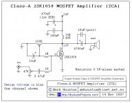
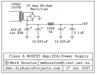
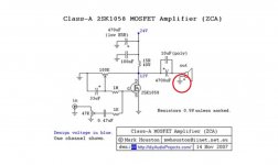
So, on post # 4 the amp circuit ( one channel shown ) and the power supply.
You can easily understand why the author called it ZCA: Zero Components Amplifier.
This is the same philosophy that inspired Nelson Pass's Zen Amplifiers:
( PassDiy )
( and Nelson himself defined this project "all very cool" here:
Class A Mosfet Amplifier and PS )
the less components on the signal path, the less distortion it will go through.
Flawless reasoning, theoretically, but then there's real life: in front of a simple T-Amp, digital amplifier where the signal is compared, chopped, filtered and re-filtered by tenth of components, the ZCA is less brilliant and detailed ( not to speak about output power, consumption, dimensions and weight ! ), but achieves more musicality, in my opinion.
Anyway don't ask me to describe a sound by words, please. Frank Zappa used to say that is like dancing the architecture ! If you are interested, please build it and listen by yourself.
Some other good points:
- it's quite simple, so everyone can build it, beginners too
- there's no need to use printed boards, it can be soldered directly or using tag stripes
- it can be bunched together with components that generally are already in your drawers
- it can be easily customized, changing Mosfet or power supply and voltages and currents, and this is the most fun !
and less good points:
- like all class A amplifiers, the power consumption is huge, with an output power of few watts. So no difficult loudspeakers: it can't manage them
- don't try to put it in a cigarette packet size case: mosfets and load resistors get quite hot, they need generously dimensioned heatsinks
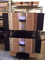
This is not necessarily a drawback, it can be a good reason to build cases as such, at last ( post # 4 ).
As for me, I choosed a less traditional configuration, but more stylish, maybe, with separate power supply, less traditional too, a little less stylish ...
In the next episodes I'll give you more details ( if someone is interested ... ), starting from the mosfet choice, as the original Hitachi 2SK1058 are out of production.
Ciao.
P.S.: for those people who can't wait, they can spoiler how the story ends here ( in italian, sorry ... )
https://melius.club/topic/315705-zc...e-da-realizzare/?tab=comments#comment-7142851
Class A Mosfet Amplifier and PS
and here:
ZCA 5 watt mosfet amp .
But I liked to refresh this fine project by Mark Houston ( AUS ) and update it:
DIY Class-A 2SK1058 MOSFET Amplifier Project .
So, on post # 4 the amp circuit ( one channel shown ) and the power supply.
You can easily understand why the author called it ZCA: Zero Components Amplifier.
This is the same philosophy that inspired Nelson Pass's Zen Amplifiers:
( PassDiy )
( and Nelson himself defined this project "all very cool" here:
Class A Mosfet Amplifier and PS )
the less components on the signal path, the less distortion it will go through.
Flawless reasoning, theoretically, but then there's real life: in front of a simple T-Amp, digital amplifier where the signal is compared, chopped, filtered and re-filtered by tenth of components, the ZCA is less brilliant and detailed ( not to speak about output power, consumption, dimensions and weight ! ), but achieves more musicality, in my opinion.
Anyway don't ask me to describe a sound by words, please. Frank Zappa used to say that is like dancing the architecture ! If you are interested, please build it and listen by yourself.
Some other good points:
- it's quite simple, so everyone can build it, beginners too
- there's no need to use printed boards, it can be soldered directly or using tag stripes
- it can be bunched together with components that generally are already in your drawers
- it can be easily customized, changing Mosfet or power supply and voltages and currents, and this is the most fun !
and less good points:
- like all class A amplifiers, the power consumption is huge, with an output power of few watts. So no difficult loudspeakers: it can't manage them
- don't try to put it in a cigarette packet size case: mosfets and load resistors get quite hot, they need generously dimensioned heatsinks
This is not necessarily a drawback, it can be a good reason to build cases as such, at last ( post # 4 ).
As for me, I choosed a less traditional configuration, but more stylish, maybe, with separate power supply, less traditional too, a little less stylish ...
In the next episodes I'll give you more details ( if someone is interested ... ), starting from the mosfet choice, as the original Hitachi 2SK1058 are out of production.
Ciao.
P.S.: for those people who can't wait, they can spoiler how the story ends here ( in italian, sorry ... )
https://melius.club/topic/315705-zc...e-da-realizzare/?tab=comments#comment-7142851
Last edited:

Valid attachments, I hope:
pic 1: amp circuit
pic 2: power supply
pic 3: big cases
pic 4: my ZCA ( front )
pic 5: my ZCA ( rear )
pic 6: my power supply ( front )
pic 7: my power supply ( rear )
pic 8: test plant
pic 1: amp circuit
pic 2: power supply
pic 3: big cases
pic 4: my ZCA ( front )
pic 5: my ZCA ( rear )
pic 6: my power supply ( front )
pic 7: my power supply ( rear )
pic 8: test plant
Attachments
-
 circuito originalissimo.jpg71.6 KB · Views: 880
 -
 alimentatore originale grosso.jpg87.2 KB · Views: 942
 -
 Amplificatoroni.jpg134 KB · Views: 705
 -
 amp fronte.jpg105.1 KB · Views: 681
 -
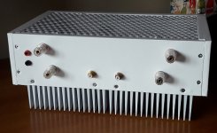 amp retro.jpg48.6 KB · Views: 708
 -
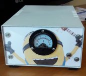 alim fronte.jpg61.6 KB · Views: 348
 -
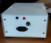 alim retro.jpg42.1 KB · Views: 348
 -
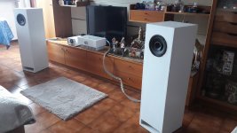 impianto.jpg623 KB · Views: 540
Which Mosfet ?
As I told you, the Hitachi 2SK1058 is no more in production, how can we replace it ?
Luckily, a good replacement is Exicon ECX10N20. This one is a lateral Mosfet too, audio specific, maybe better than Hitachi as it’s more recent ( on the web they find it more brilliant ).
You can buy it directly on Exicon site.
Someone might say “ … but on E-Bay there’s plenty of 2SK1058, low priced too”.
Well, I tell you that 90 % are fake, and I’m not telling because I heard it through the grapewine, but for personal experience.
I bought 2 pairs from a site, put them into a test ZCA, where previous mosfets IRF740F1 and SIHA2N80E worked properly: no sound at all.
So I bought one more pair from a site that claimed “original Hitachi 2SK1058”: no sound again, but they refunded me, al least.
Why don’t they work ?
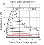
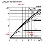
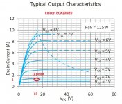
Looking at the output characteristics of the original 2SK1058 ( pic 1 ), we find out that with Vds = 12 Vcc and Vgs = 1.5 Vcc, we should measure an Id current about 1 A.
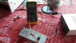
Well, the Id that I measured, with the fake ones, was between 7 and 9 A ( pic 2 ) !
So, to make the circuit work, we should lower the 15 ohms load R to 1 or 2 ohms, with power consumption that jumps to the moon.
Note: if you would like to make this test, switch on the circuit for no more than 1 sec, otherwise it’s easy to blow up mosfets, generators and meter.
Can we distinguish good 2SK1058 from fake only looking at their pictures ? I should say no: all the methods that I found on the web are different and in contradiction with each other.
A good method could be to measure input and output capacity, well explained here:
Suzy's Blog: More fakes
Original Hitachi have Cgs around 0.8 nF and Cgd around 0.6 nF. Fake ones have Cgs between 3.2 e 6.5 nF and Cgd between 2.3 e 5.5 nF ( pic 3 ).
Anyway, this project can fit to different Mosfets, by adapting power supply and load R. As I told you, my starting circuit with IRF740F1 or SIHA2N80E was quite satisfying.
We’ll talk about it later, dealing with the possible evolutions.
Next episode: how to build the case.
Ciao.
As I told you, the Hitachi 2SK1058 is no more in production, how can we replace it ?
Luckily, a good replacement is Exicon ECX10N20. This one is a lateral Mosfet too, audio specific, maybe better than Hitachi as it’s more recent ( on the web they find it more brilliant ).
You can buy it directly on Exicon site.
Someone might say “ … but on E-Bay there’s plenty of 2SK1058, low priced too”.
Well, I tell you that 90 % are fake, and I’m not telling because I heard it through the grapewine, but for personal experience.
I bought 2 pairs from a site, put them into a test ZCA, where previous mosfets IRF740F1 and SIHA2N80E worked properly: no sound at all.
So I bought one more pair from a site that claimed “original Hitachi 2SK1058”: no sound again, but they refunded me, al least.
Why don’t they work ?
Looking at the output characteristics of the original 2SK1058 ( pic 1 ), we find out that with Vds = 12 Vcc and Vgs = 1.5 Vcc, we should measure an Id current about 1 A.
Well, the Id that I measured, with the fake ones, was between 7 and 9 A ( pic 2 ) !
So, to make the circuit work, we should lower the 15 ohms load R to 1 or 2 ohms, with power consumption that jumps to the moon.
Note: if you would like to make this test, switch on the circuit for no more than 1 sec, otherwise it’s easy to blow up mosfets, generators and meter.
Can we distinguish good 2SK1058 from fake only looking at their pictures ? I should say no: all the methods that I found on the web are different and in contradiction with each other.
A good method could be to measure input and output capacity, well explained here:
Suzy's Blog: More fakes
Original Hitachi have Cgs around 0.8 nF and Cgd around 0.6 nF. Fake ones have Cgs between 3.2 e 6.5 nF and Cgd between 2.3 e 5.5 nF ( pic 3 ).
Anyway, this project can fit to different Mosfets, by adapting power supply and load R. As I told you, my starting circuit with IRF740F1 or SIHA2N80E was quite satisfying.
We’ll talk about it later, dealing with the possible evolutions.
Next episode: how to build the case.
Ciao.
Attachments


How to build the case
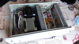
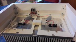
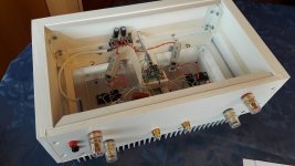
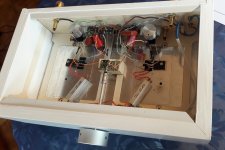
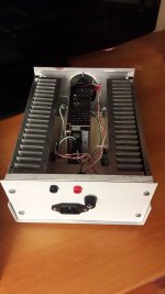
Since the beginning, on a test circuit with IRF740F1, great heatsinks were mandatory, so your case will have to do with this need.
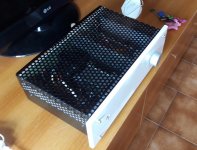
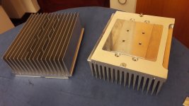
My first prototype was housed in an ordinary case for electronics, but I didn’t like it: too ordinary and too heavy ( pic 1 and 2 ).
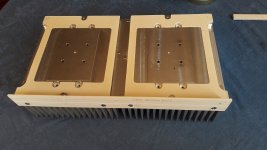
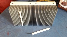
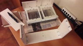
I resolved to separate power supply from amp, so to use 2 big heatsinks that I bought used, as a new one with those dimensions costs a lot ( pic 3 and 4 ).
Please see pictures to follow the evolution of the case, made with poplar wood boards covered with adhesive plastic sheets.
Ciao.
Next episode: more pictures about the building of the case
Since the beginning, on a test circuit with IRF740F1, great heatsinks were mandatory, so your case will have to do with this need.
My first prototype was housed in an ordinary case for electronics, but I didn’t like it: too ordinary and too heavy ( pic 1 and 2 ).
I resolved to separate power supply from amp, so to use 2 big heatsinks that I bought used, as a new one with those dimensions costs a lot ( pic 3 and 4 ).
Please see pictures to follow the evolution of the case, made with poplar wood boards covered with adhesive plastic sheets.
Ciao.
Next episode: more pictures about the building of the case
Attachments
-
 prima versione.jpg142.2 KB · Views: 210
 -
 telaio prima versione.jpg271.1 KB · Views: 185
 -
 radiatori.jpg203.7 KB · Views: 198
 -
 dissipatori uniti.jpg219.9 KB · Views: 133
 -
 dorsini.jpg281.6 KB · Views: 185
 -
 legni.jpg198.6 KB · Views: 173
 -
 fronte interno.jpg183.2 KB · Views: 190
 -
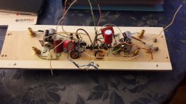 tavola posteriore.jpg201.7 KB · Views: 186
Last edited:
More pictures.
The potentiometer is DACT Type, made of SMD resistors: no unbalanced channels at low volume and no noise when aging.
Pay attention: this is an inverting amp so, to have the correct phase at the output, you must connect the output signal to the – binding post and the ground to the + ( see last pic ).
Ciao.
Next episode: how to build the power supply
Attachments
Member
Joined 2009
Paid Member
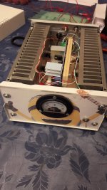
Linear power supply
This kind of circuit is quite sensitive to power supply noise, so it needs a very silent one.
In my first tests, performed with IRF740F mosfet, 3 Ω R load and 14 Vcc, I used a linear power supply ( so no regulators, only transformer [ 220 - 12 Vac, 100 VA ], diode bridge, capacitors and inductor ) and 3 capacitors 10,000 µF each.
You might say that with a 12 Vac transformer, we should expect 17,5 Vcc as power supply. Right, but with a current around 2,5 A fed to each channel, it “sat down” to 14 Vcc, even though the transformer was rated as 100 VA.
Trimming the gate potentiometers, we divide these 14 Vcc in 7 V on the load R ( so Id = 7/3 = around 2,3 A each channel ) and 7 V between drain and source of the mosfet ( pic 1: Q point of the device ).
Result: some noise from the loudspaeakers, a bit too high to my taste.
Putting a 100 mH inductance ( the black box in pic 2 ), silence was achieved.
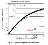
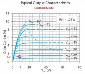
The same with Vishay SiHA2N80E and Exicon ECX10N20 mosfets, but with a 220 – 24 Vac / 200 VA transformer and 15 ohm R load.
The power supply sat down to 30 Vcc for the same reason as before. Trimming the gate potentiometer, they were divided into 15 V on Rl ( so to have Id = 15V / 15 ohm = 1 A each channel ) and 15 V between drain and source ( pic 3 and 4: Q point ).
Next episode: regulated power supply.
Ciao.
This kind of circuit is quite sensitive to power supply noise, so it needs a very silent one.
In my first tests, performed with IRF740F mosfet, 3 Ω R load and 14 Vcc, I used a linear power supply ( so no regulators, only transformer [ 220 - 12 Vac, 100 VA ], diode bridge, capacitors and inductor ) and 3 capacitors 10,000 µF each.
You might say that with a 12 Vac transformer, we should expect 17,5 Vcc as power supply. Right, but with a current around 2,5 A fed to each channel, it “sat down” to 14 Vcc, even though the transformer was rated as 100 VA.
Trimming the gate potentiometers, we divide these 14 Vcc in 7 V on the load R ( so Id = 7/3 = around 2,3 A each channel ) and 7 V between drain and source of the mosfet ( pic 1: Q point of the device ).
Result: some noise from the loudspaeakers, a bit too high to my taste.
Putting a 100 mH inductance ( the black box in pic 2 ), silence was achieved.
The same with Vishay SiHA2N80E and Exicon ECX10N20 mosfets, but with a 220 – 24 Vac / 200 VA transformer and 15 ohm R load.
The power supply sat down to 30 Vcc for the same reason as before. Trimming the gate potentiometer, they were divided into 15 V on Rl ( so to have Id = 15V / 15 ohm = 1 A each channel ) and 15 V between drain and source ( pic 3 and 4: Q point ).
Next episode: regulated power supply.
Ciao.
Attachments
Regulated power supply
In this project, the power supply must supply a constant voltage of course, and in particular a constant current, that will not change with the amplitude of the input signal: the output current is subtracted by this constant amount. That’s why the output signal is phase inverted with respect to the input.
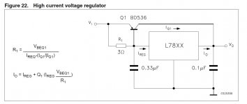
So, why not build the power supply simply using an SMPS ( quite noisy ) and a voltage regulator, as suggested by OldDIY ? It’s simpler, cheaper, with less unstable V and I and maybe smaller, even though heatsinks for the regulators are mandatory.
I started with a 24 V – 6 A SMPS and LM7815 - 15 V regulators. The circuit was adapted to 15 Vcc: 3 Ω load R, 7.5 V on Rl and Vds ( trimming the gate potentiometers ), Id 2.5 A each channel (7.5 V / 3 Ω = 2.5 A) ( pic 1 and 2 ).
A single LM7815 can supply a little more than 1 A. To reach 2.5 A for each channel, I shunted 4 of them.
Note: I know it’s not particularly fair to shunt V regulators, unless their output is absolutely the same, but putting a 10 or 20 KΩ resistor on their output, those little mismatches get balanced, even when the power supply is not connected to the amp.
Anyway, for those who are still skeptical, it’s easy to increase the output current of a voltage regulator using a resistor and a power BJT: you can find the schematic on their datasheets ( pic 3 ).
How did it work ? Quite silent and stable, but a little too hot for its little case. After half an hour working, the regulators switched in thermal protection.
So I turned to MC7818 – 18 V regulators, with 7 Ω load R, 9 V on Rl and Vds ( trimming the gate potentiometers ), Id 1.3 A each channel ( 9 V / 7 Ω = 1.28 A )( pic 4 and 5 ).
Now only 2 shunt regulators are enough, and a 24V / 3A SMPS, with its output trimmed to 20.5 V: much less heat to dissipate and no more thermal protection issues.
Next ( and last ) episode: customizing the original circuit.
Ciao.
In this project, the power supply must supply a constant voltage of course, and in particular a constant current, that will not change with the amplitude of the input signal: the output current is subtracted by this constant amount. That’s why the output signal is phase inverted with respect to the input.
So, why not build the power supply simply using an SMPS ( quite noisy ) and a voltage regulator, as suggested by OldDIY ? It’s simpler, cheaper, with less unstable V and I and maybe smaller, even though heatsinks for the regulators are mandatory.
I started with a 24 V – 6 A SMPS and LM7815 - 15 V regulators. The circuit was adapted to 15 Vcc: 3 Ω load R, 7.5 V on Rl and Vds ( trimming the gate potentiometers ), Id 2.5 A each channel (7.5 V / 3 Ω = 2.5 A) ( pic 1 and 2 ).
A single LM7815 can supply a little more than 1 A. To reach 2.5 A for each channel, I shunted 4 of them.
Note: I know it’s not particularly fair to shunt V regulators, unless their output is absolutely the same, but putting a 10 or 20 KΩ resistor on their output, those little mismatches get balanced, even when the power supply is not connected to the amp.
Anyway, for those who are still skeptical, it’s easy to increase the output current of a voltage regulator using a resistor and a power BJT: you can find the schematic on their datasheets ( pic 3 ).
How did it work ? Quite silent and stable, but a little too hot for its little case. After half an hour working, the regulators switched in thermal protection.
So I turned to MC7818 – 18 V regulators, with 7 Ω load R, 9 V on Rl and Vds ( trimming the gate potentiometers ), Id 1.3 A each channel ( 9 V / 7 Ω = 1.28 A )( pic 4 and 5 ).
Now only 2 shunt regulators are enough, and a 24V / 3A SMPS, with its output trimmed to 20.5 V: much less heat to dissipate and no more thermal protection issues.
Next ( and last ) episode: customizing the original circuit.
Ciao.
Attachments
Customization
If you had enough patience to read this topic till here, maybe you realized by yourself that ZCA is easily customizable, either on power supply type and voltage or mosfets to use.
We already dealt with power supply type.
About the power supply voltage: the designer M. Houston says that the best performance is achieved with 24 Vcc.
You can lessen it in order to limit the power consumption and heat to drain, but be careful not to lessen too much, or the output signal risks to be too compressed. As a thumb rule, choose a Vds voltage at least 4 V more than the gate threshold voltage of the mosfet.
Another drawback with low Vcc, is the volume knob rotation: with a 12 V Vcc and an MP3 player as signal source, I had to rotate it till 3 o’clock to have an ordinary output volume.
As for the usable mosfets, you can choose among those with the following features:
- N channel
- TO220 package or like
- gate threshold voltage ( Vgsth ) not too high, a value between 1 and 2 V is good, but it’s not mandatory, if Vcc is high enough.
The best choice remains lateral mosfets like Exicons, built for audio purposes.
Vcc and mosfet must match, of course, so always check on their output characteristics that Vgs, Vds and Id lay in the linear area.
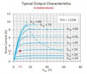
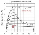
As an example, looking at the original project, with Vcc = 24 V ( so Vds = V load R = 12 V ), 15 Ω load R and 2SK1058 mosfets, we get an Id around 12 V / 15 Ω = 0.8 A.
The output characteristics in pic 1 show a Vgs around 1.7 V and it’s fine, as it’s over the 2SK1058 Vgsth ( 1.45 V ).
Would you like to double the current Id, to make the sound more brilliant and powerful ( and to double power consumption and heat … ) ?
With 24 V as Vcc, just divide by 2 Rl value, so 7 Ω, Id becomes 12 V / 7 Ω = 1.7 A and the Q point moves as in pic 2, with Vgs = 3 V, remaining in the linear area.
I already told you that you can divide Vcc equally among load R and mosfet Vgs by trimming the gate potentiometer. A good way is to check and trim every 15 minutes, only the first time that you turn it on of course, to see the changes due to increasing temperature. When variations are over, close the lid of the case: the amp is ready.
That’s all, folks: now you’ve got an easy to build and cheap class A toy to play with and to customize as you like.
Thanks everyone for reading and participating. As for me, I’m still using it in my personal audio corner: the speaker position is not legal, but the living room is always occupied by a wife, 2 daughters and 3 cats, until the outside world situation gets better …
Ciao.
If you had enough patience to read this topic till here, maybe you realized by yourself that ZCA is easily customizable, either on power supply type and voltage or mosfets to use.
We already dealt with power supply type.
About the power supply voltage: the designer M. Houston says that the best performance is achieved with 24 Vcc.
You can lessen it in order to limit the power consumption and heat to drain, but be careful not to lessen too much, or the output signal risks to be too compressed. As a thumb rule, choose a Vds voltage at least 4 V more than the gate threshold voltage of the mosfet.
Another drawback with low Vcc, is the volume knob rotation: with a 12 V Vcc and an MP3 player as signal source, I had to rotate it till 3 o’clock to have an ordinary output volume.
As for the usable mosfets, you can choose among those with the following features:
- N channel
- TO220 package or like
- gate threshold voltage ( Vgsth ) not too high, a value between 1 and 2 V is good, but it’s not mandatory, if Vcc is high enough.
The best choice remains lateral mosfets like Exicons, built for audio purposes.
Vcc and mosfet must match, of course, so always check on their output characteristics that Vgs, Vds and Id lay in the linear area.
As an example, looking at the original project, with Vcc = 24 V ( so Vds = V load R = 12 V ), 15 Ω load R and 2SK1058 mosfets, we get an Id around 12 V / 15 Ω = 0.8 A.
The output characteristics in pic 1 show a Vgs around 1.7 V and it’s fine, as it’s over the 2SK1058 Vgsth ( 1.45 V ).
Would you like to double the current Id, to make the sound more brilliant and powerful ( and to double power consumption and heat … ) ?
With 24 V as Vcc, just divide by 2 Rl value, so 7 Ω, Id becomes 12 V / 7 Ω = 1.7 A and the Q point moves as in pic 2, with Vgs = 3 V, remaining in the linear area.
I already told you that you can divide Vcc equally among load R and mosfet Vgs by trimming the gate potentiometer. A good way is to check and trim every 15 minutes, only the first time that you turn it on of course, to see the changes due to increasing temperature. When variations are over, close the lid of the case: the amp is ready.
That’s all, folks: now you’ve got an easy to build and cheap class A toy to play with and to customize as you like.
Thanks everyone for reading and participating. As for me, I’m still using it in my personal audio corner: the speaker position is not legal, but the living room is always occupied by a wife, 2 daughters and 3 cats, until the outside world situation gets better …
Ciao.
Attachments

- Home
- Amplifiers
- Solid State
- ZCA: simple and easy to build class A single Mosfet amplifier