Well, I guess there's little new under the sun.
The inductors are wound aiming for a square cross section, made of 1.9mm wire. I have chosen to protect them a bit from scratches and the like by wrapping them in cotton tape prior to impregnating them with polyurethane compound.
The basic specs are: 2*80mH (nominal) at 100Hz they measure approx 2*120mH These numbers are approx. as my sine generator have not been calibrated for ages and I have no way to tell how far it's off.
The DCR is 2.3 ohm
They tip the scales at approx. 20kg.
They are good for at least 20ADC without getting more than luke warm. Most likely they are good for almost 30ADC, but I have no way to test this.
And a pic of the beast in question:
http://www.briangt.com/gallery/magura-inductors/PICT0057
Magura")
The inductors are wound aiming for a square cross section, made of 1.9mm wire. I have chosen to protect them a bit from scratches and the like by wrapping them in cotton tape prior to impregnating them with polyurethane compound.
The basic specs are: 2*80mH (nominal) at 100Hz they measure approx 2*120mH These numbers are approx. as my sine generator have not been calibrated for ages and I have no way to tell how far it's off.
The DCR is 2.3 ohm
They tip the scales at approx. 20kg.
They are good for at least 20ADC without getting more than luke warm. Most likely they are good for almost 30ADC, but I have no way to test this.
And a pic of the beast in question:
http://www.briangt.com/gallery/magura-inductors/PICT0057
Magura
Magura said:.........................
And a pic of the beast in question:
http://www.briangt.com/gallery/magura-inductors/PICT0057
Magura
ha!
try that with 0,8mm wire .....

ugly!
Zen Mod said:
ha!
try that with 0,8mm wire .....
ugly!
0.8mm wire would leave you with somewhat less sore hands
Magura
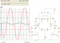
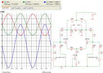
I know that this thread is old news, but I've been exploring with a simulator and have discovered what seems to be better ways of setting up this amplifier. Schematic below has balanced input at 2.5 volts. BTW, my original amp doesn't sim very well, this is much better! Admittedly, I'm still testing and there are probably things I've overlooked. Still, this sim business is a whole bunch of fun!
Admittedly, I'm still testing and there are probably things I've overlooked. Still, this sim business is a whole bunch of fun!Attachments
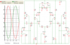
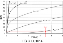
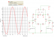
So I thought I'd play with the most simple version of the ZV7-T -- a version with the big 1000 V/Z Plitrons and a pair of Loveltech LU1014D transistors. I employed a 5 volt power supply (ha) to keep the transistor in the concave portion of it's ID/VDS curve. I'll breadboard it this weekend.
The sim says that the LU1014D transistor power consumption is 7 watts per device -- just about where the ZV8 operates.
This idea came about because I have 110 db, 1W1M horns and only require a watt or two of power. This amp delivers approx. two watts, or so. Might be wonderful, who knows?
There seems to be a phase issue. All suggestions are welcome.
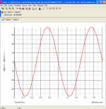
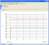
Here's a bunch of sim pics:
The sim says that the LU1014D transistor power consumption is 7 watts per device -- just about where the ZV8 operates.
This idea came about because I have 110 db, 1W1M horns and only require a watt or two of power. This amp delivers approx. two watts, or so. Might be wonderful, who knows?
There seems to be a phase issue. All suggestions are welcome.
Here's a bunch of sim pics:
Attachments
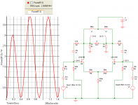
I made a mistake: the choke shown in the prior schematics is rated at 200 micro-henries (per leg) instead of 200 milli-henries. The larger choke changes everything. On a brighter note, the 200 micro-henry choke can be a very small air-core fellow with less distortion than that of the Plitron, iron-core transformer.
I'm still impressed with the concept.
I'm still impressed with the concept.
Zen Mod said:CCS in tale?
I'm exploring that concept, Choky. It's very simple for me to add another LU1014D to the tail.
Thanks for taking the time to read and respond to my tiny, itzi-bitzi offering.
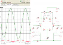
Hi Carpenter !
You have connected the current source j fet wrong. The gate should be neutral or slightly negative compared to the source. The way you have done it, the gate is 5 volts more positive than the source, and the j fet is completely open.
Keep on.
Thorsten Larsen
You have connected the current source j fet wrong. The gate should be neutral or slightly negative compared to the source. The way you have done it, the gate is 5 volts more positive than the source, and the j fet is completely open.
Keep on.
Thorsten Larsen
- Status
- This old topic is closed. If you want to reopen this topic, contact a moderator using the "Report Post" button.
- Home
- Amplifiers
- Pass Labs
- ZV7-T (transformer)