Hello everyone,
I’m having trouble configuring my Ucpure QUAD to output 3.3 V instead of 5 V. Here’s what I’ve done so far:
Is there another step I’m missing or a common pitfall when switching voltage on the QUAD? Any suggestions would be greatly appreciated. Thanks!
I’m having trouble configuring my Ucpure QUAD to output 3.3 V instead of 5 V. Here’s what I’ve done so far:
- Initial setup
- The jumpers were all open, so the board was set to 5 V by default.
- Switching to 3.3 V
- Powered down the unit (switched off S1 and unplugged).
- Installed four jumpers as per the manual: two on J14 and two on J15.
- Ensured each jumper bridged pins 1–2 and 3–4 correctly.
- Powering back up
- Reconnected and powered on the QUAD and power on S1.
- Reconnected and powered on the QUAD and power on S1.
Is there another step I’m missing or a common pitfall when switching voltage on the QUAD? Any suggestions would be greatly appreciated. Thanks!
I'm looking at the manual, and I don't know what you could have done wrong. Only thing I can think of, is you have the jumper orientation wrong.
I’ve double‑checked the jumper orientation several times and I’m confident it’s correct.I'm looking at the manual, and I don't know what you could have done wrong. Only thing I can think of, is you have the jumper orientation wrong.
Do I need to discharge the capacitors? I’m beginning that process now.
Perhaps it’s necessary to discharge them before switching from 5 V to 3.3 V.
I’d really like to test this power supply at 3.3 V.
Use a automotive 6 or 12 v light bulb to drain the capacitors down to at least 3v
Drain them in series where the lug nuts are to ensure equal voltage on both caps.
Drain them in series where the lug nuts are to ensure equal voltage on both caps.
Helo @Gabster 2000 ,
Thanks a lot for the tip.
So, to run the UcpureQUAD—which was working at 5 V—at 3.3 V, do I always need to discharge the capacitors before switching to 3.3 V?
I’ve been using them at 5 V and the D9 PURE LED is on, so they’re fully charged.
At this point, to make them work on 3.3 V, is it just a matter of draining the capacitors and then adjusting the jumpers?
Correct
I would not bounce back an forth decide if they will be used for 5v Or 3.3v
Check the voltage that it is 3.3 or close to it before connecting them to avoid sending 5v to a 3.3v board and frying it by accident.
Connect the cable to charge between songs and breaks that will keep the voltage from drifting down too much a critical part
The Quad is best used for the FifoPi/clocks 3.3v for the Dac like Dual mono Dac I would rather use 2 separate 5v rather then 1 quad to feed the 2 separate Dac supplies
Hope that helps have fun
@Gabster 2000 ,
Can I leave the 6–12 V lamp mounted on the Ucpure Quad board, or should I remove the caps from the board for do this?
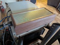
If I do connect the lamp while it’s still on the board, where would you recommend I attach the positive and negative leads, based on this image:

Thankss!!!
Can I leave the 6–12 V lamp mounted on the Ucpure Quad board, or should I remove the caps from the board for do this?
If I do connect the lamp while it’s still on the board, where would you recommend I attach the positive and negative leads, based on this image:
Thankss!!!
You can use either J10 or J13 ( either one they are connected together) these are connected directly to the caps or The easiest remove 2 plastic caps ( 1 + 1- ) on the top main board and put the bulb on any positive and negative.
The 2 banks of Caps are connected in parallel (The 2+are connected together same with the2 -) so you will be draining all 4 caps this way (avoid any shorts your wire will burn instantly and you can burn your fingers if not worse) as there is no fuse on J10 and 13 same for the cap screws you are connected directly to the caps so be careful shorting anything.
Do not leave the bulb permanently this is just temporary to drain them till you get around 3v.
I think most of us same for me the first time i saw it think because there are 2 output terminals that these are 2 independent supplies they are Not they are the same Connected in Parallel The Advantage of the Quad is you have more Storage capacity so they last longer and less voltage drift, also half the ESR. They are Ideal for the FifoQ7 3.3v Clocks or other applications where you want the lowest ESR and bigger storage Capacity
Last edited:

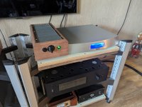
external case for the power supply lumin s1 case also almost ready.
it has a dual pcm 1794A in it and is controlled by an ian canada purepi-ll and a fifoPiMa.
it has a dual pcm 1794A in it and is controlled by an ian canada purepi-ll and a fifoPiMa.
Attachments


- Home
- Source & Line
- Digital Line Level
- Asynchronous I2S FIFO project, an ultimate weapon to fight the jitter