9460 signal without outputs in board. Using speaker negative terminal as ground. As soon I install one mosfet each on either side all the voltages dipping. I cannot on the amp direct without limiting resistor as theat will blow all the outputs in no time.
Attachments
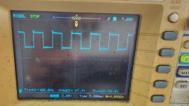
I think the overshoot on the neg drive is insufficient gate resistance combined with the lower gate capacitance of the P ch device. This is compared to the N ch which usually has higher gate capacitance in comparison.
I would extend the scope time base to look at the ringing and identify the frequency. Shouldn't be hard to compensate with more series R to gate. Up to 100R shouldn't be a problem at that specific switching frequency. This is common to do with P ch vs N ch hexfet devices, so you end up with different gate resistors. The PCB layout can also have alot to do with it. The secondary supply side is usually isolated on these car amps, so the ground point should be right after the rectifier at the common connection of main filter caps.
I would extend the scope time base to look at the ringing and identify the frequency. Shouldn't be hard to compensate with more series R to gate. Up to 100R shouldn't be a problem at that specific switching frequency. This is common to do with P ch vs N ch hexfet devices, so you end up with different gate resistors. The PCB layout can also have alot to do with it. The secondary supply side is usually isolated on these car amps, so the ground point should be right after the rectifier at the common connection of main filter caps.
Yes I can find one. What components do I need to change.Do you have a junk amp laying around that you could modify slightly to make a signal generator?
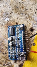
It simply needs to have a working TLx94 IC (no PS FETs) and would require changing the value of the timing components.
This may not come to anything but it cost virtually nothing and I want to see what's different with full rail voltage.
Change Ct and Rt (on pins 5 and 6) to get the frequency up around 100k on pins 9 and 10.
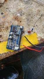
You'll need a small cap 1000pf to 0.01uf to load the output locations. All you need is one. The value isn't critical.
Do you have a second probe and second working channel on the scope?
You'll also need a resistor of about 100k and a 0.1uf cap to put in series with the output of the 494.
Change Ct and Rt (on pins 5 and 6) to get the frequency up around 100k on pins 9 and 10.
You'll need a small cap 1000pf to 0.01uf to load the output locations. All you need is one. The value isn't critical.
Do you have a second probe and second working channel on the scope?
You'll also need a resistor of about 100k and a 0.1uf cap to put in series with the output of the 494.

You'll connect the small 1000pf (or whatever you have) across the gate and source of the outputs being checked, You'll check the gate signal with the scope.
Make sure that both channels deflect exactly the same to the rail. Then probe the rail with one channel and the gate with the other channel. Post a photo of the scope display.
The output from this oscillator will go to the non-inverting input (pin 3) of the TL072.
Make sure that both channels deflect exactly the same to the rail. Then probe the rail with one channel and the gate with the other channel. Post a photo of the scope display.
The output from this oscillator will go to the non-inverting input (pin 3) of the TL072.


- Home
- General Interest
- Car Audio
- CT Sounds AT900-1D