I could use the following trafos in series (I've this) for testing:
- 250 Vac @ 400 mA
- 60 Vac @ 8 A (500VA)
In this way I would obtain a more prudent secondary (250 + 60) * 1.41 = 435 Vdc.
Could the fact that the 2 trafos are completely different cause any problems? Of course for the first start up and some measurement / calibration of one channel.
- 250 Vac @ 400 mA
- 60 Vac @ 8 A (500VA)
In this way I would obtain a more prudent secondary (250 + 60) * 1.41 = 435 Vdc.
Could the fact that the 2 trafos are completely different cause any problems? Of course for the first start up and some measurement / calibration of one channel.
I've -60Vdc at the output of PSU of negative grid but -35Vdc max at the pin 5 of el34.
I used 50 Vac secondary for this PSU. If I start the amp, the voltage across the 10 ohm cathode resistor rises rapidly and exceeds the target of 400 mV, but of course I turn OFF immediatly at 400 mV.
You think that 50Vac secondary it's too short to obtain -60V at the pin 5?
I used 50 Vac secondary for this PSU. If I start the amp, the voltage across the 10 ohm cathode resistor rises rapidly and exceeds the target of 400 mV, but of course I turn OFF immediatly at 400 mV.
You think that 50Vac secondary it's too short to obtain -60V at the pin 5?
Not sure why this would be according to schematic you should be able to get P2 down all the way to the negative rail. Don't fit the EL34 until OK, you have a high impedance voltmeter. Whats the voltage across C11? Sorry reading it wrong hold on...
Yep check voltage at C11 first. Check value of P3 and P2. R22, R17 and R18 check too - they will reduce the voltage a bit but not to that extent - chances are youu have a wrong component. -60V at the PSU output is fine.
Yep check voltage at C11 first. Check value of P3 and P2. R22, R17 and R18 check too - they will reduce the voltage a bit but not to that extent - chances are youu have a wrong component. -60V at the PSU output is fine.
Last edited:
.png")
No error, it's the DMM that gives me the wrong value of -35 Vdc.
I simulated the circuit and then cheked the voltage on R17, R18 but with another DMM and correspond exatly to sumulation (different impedance of two DMM?).
All other measurements with the two DMMs correspond . Therefore I would rule out failures of the DMM.
Such a thing has never happened to me. What do you think?
I simulated the circuit and then cheked the voltage on R17, R18 but with another DMM and correspond exatly to sumulation
(different impedance of two DMM?).All other measurements with the two DMMs correspond . Therefore I would rule out failures of the DMM.
Such a thing has never happened to me. What do you think?
Attachments

Some tests with 425 Vdc B+:
1- bias voltage measured at pin 5 without tubes -53V (both tube)
2- voltage measured at cathode resistors 380 mV and 340 mV with -53V bias (too high) .
3- bias voltage measured at pin 5 with tubes fitted -53V (both tube)
I do not understand.
We are in the red zone and the el34 should be almost off.
Correct?
What's going on?
1- bias voltage measured at pin 5 without tubes -53V (both tube)
2- voltage measured at cathode resistors 380 mV and 340 mV with -53V bias (too high)
.3- bias voltage measured at pin 5 with tubes fitted -53V (both tube)
I do not understand.
We are in the red zone and the el34 should be almost off.
Correct?
What's going on?
Attachments

Is the socket wired correctly? How is the screen connected, and have you measured the voltage drop over the screen grid stopper?
I had a case where I had a tube that tested fine sometimes, but had no curves other times, and that was due to a poor joint in one of the octal pins. But that is likely to be a one off.
Maybe a photo?
I had a case where I had a tube that tested fine sometimes, but had no curves other times, and that was due to a poor joint in one of the octal pins. But that is likely to be a one off.
Maybe a photo?
Hi guys,
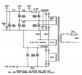
Good news I found the cause, it was the input resistor circled in red that I hadn't soldered yet. Now the bias works perfectly. I gradually set the bias to 300mV for the first tests and everything seems ok. It seems to sound very good (with a landfill speaker) and is absolutely silent, no hum no noise .... I am attaching some images of the prototype. Look at that Frankenstein PSU, but it works well for testing.
Good news I found the cause, it was the input resistor circled in red that I hadn't soldered yet. Now the bias works perfectly. I gradually set the bias to 300mV for the first tests and everything seems ok. It seems to sound very good (with a landfill speaker) and is absolutely silent, no hum no noise .... I am attaching some images of the prototype. Look at that Frankenstein PSU
, but it works well for testing.Attachments

Thank you,
now I use this and it looks very good to me:
TTG-EL34PP - Tube output transformer [6,6kOhm] 2xEL34 / 2x6L6 Push-pull or similar - Shop Toroidy.pl
we will see how it sounds with decent speaker and good source.
now I use this and it looks very good to me:
TTG-EL34PP - Tube output transformer [6,6kOhm] 2xEL34 / 2x6L6 Push-pull or similar - Shop Toroidy.pl
we will see how it sounds with decent speaker and good source.
- Home
- Amplifiers
- Tubes / Valves
- Elektor Claus Byrith 4-30