I'd love to hear those alongside the ones I used – they're considerably cheaper.
30W 6600 Ohms Ultra Linear Push Pull Output transformer – Primary Windings
30W 6600 Ohms Ultra Linear Push Pull Output transformer – Primary Windings
Hi,
I bought the power transformer:
TSTA 0250/001 - Mains transformer for tubes - Shop Toroidy.pl
If I do not use some 6.3Vac secondary temporarily or permanently, I can leave it open or it is better to close it with an adequate resistor? For example 6.3Vac with a 1K resistor to ensure the circulation of a minimal current.
On the final build I would like to feed the filaments of the two channels with two separate 6.3Vac (7A) secondaries, but temporarily for the tests of one channel at a time I need one only.
Hi. I used a multimeter and a pair of very cheap in-ear headphones. This is what I did.Hello everyone
finally after some time I can go back to building my amplifier.
willholmania, please, what method did you use to set AC balance?
Thanks
- Distortion meter
- Multimeter
- Headphones
Short phono inputs to ground and connect dummy 8Ω loads to speaker outputs.
Measure exact value of 10Ω resistors R24 and R25. (10.1Ω)
Set P3 to midpoint and P2 fully clockwise.
Connect DVM between TP0 and TP3, rotate P2 until it reads 404mV = 40mA.
Repeat process with DVM between TP0 and TP4.
Put DVM across TP3 and TP4 and adjust P3 until it reads 0v.
Let amp warm up for 20 mins. Repeat all of the above but this time set current to 50mA. 505mV = 50mA.
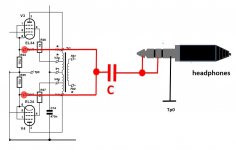
With a 1kHz test signal on the input connect tip of headphone socket to TP3 and TP4 simultaneously, negative of headphones to TP0. Adjust P1 for quietest signal. 1uF capacitor inline with headphones tip will eliminate DC in headphones.
With a 1kHz test signal on the input connect tip of headphone socket to TP3 and TP4 simultaneously, negative of headphones to TP0. Adjust P1 for quietest signal. 1uF capacitor inline with headphones tip will eliminate DC in headphones.
Thanks, my question was only for AC balance. I had already adjusted the DC balance.
So the headphone connection diagram should be as follows right?

See page 24Thanks, my question was only for AC balance. I had already adjusted the DC balance.
So the headphone connection diagram should be as follows right?
View attachment 1048316
Attachments
Hi,
I,ve put an ALPS rk27 100k into my amp and about half the volume he emits bzzz. If the potentiometer it's external no noise neither at max volume, so it is a potentiometer shielding problem. Any suggestions, please, on how to make the shield? The shield must be connected to the main ground psu?
This is the elektor publication:

But it's not very clear
Thanks
I,ve put an ALPS rk27 100k into my amp and about half the volume he emits bzzz. If the potentiometer it's external no noise neither at max volume, so it is a potentiometer shielding problem. Any suggestions, please, on how to make the shield? The shield must be connected to the main ground psu?
This is the elektor publication:

But it's not very clear
Thanks
I didn't fit one, although I wish I had so I think you should stick with it. However, mounting it so close to the power transformer seems daft to me. As the outputs from it have to go virtually up to the front panel to get to the amp PCBs, I'd mount it on the front panel and keep the input signals well away from that power transformer.
It is a real bad choice electrically and ergonomically. In fact, in my amp the pot is located in the front panel and very far from the main transformer.I didn't fit one, although I wish I had so I think you should stick with it. However, mounting it so close to the power transformer seems daft to me. As the outputs from it have to go virtually up to the front panel to get to the amp PCBs, I'd mount it on the front panel and keep the input signals well away from that power transformer.
Without pot and with a tube preamp or directly to DAC, no hum, no noise even with the max volume. Even with the pot outside the case it is silent.
I would like to try to shield it otherwise I'll take it off.
Guys,
I tried to put a RK27 10K instead of 100K in to the amp and.........NO NOISE at any volume .
.
So I think I keep this.
Now it sounds as integrated amplifier and the sound is always great (with 1663 PP Lundahl's).
The output impedance of my DAC it's 50 Ohm, therefore no interfacing problems.
I tried to put a RK27 10K instead of 100K in to the amp and.........NO NOISE at any volume
So I think I keep this.
Now it sounds as integrated amplifier and the sound is always great (with 1663 PP Lundahl's).
The output impedance of my DAC it's 50 Ohm, therefore no interfacing problems.
Last edited:
That looks very much like Mullard stuff to me. Either their circuit, or a modification thereof.
And, the 82k resistor in the phase splitter cathodes is not a very good Constant Current Sink (not a good CCS).
With no True CCS, that is the only reason why there is a potentiometer in the plate loads of the phase splitter.
(Balance of a phase splitter with true CCS and 0.1% precision plate resistors is Intrinsic; near perfect balance).
- Home
- Amplifiers
- Tubes / Valves
- Elektor Claus Byrith 4-30