Well, I never imagined that this simple query would result in such an interesting and protracted discussion! However, I think what needed is someone actually comparing a linear & SMP psu side by side to evaluate and come out with some solid results! I'm sure some of you may have already done this or even published results are out there?
I, having constructed & used linear psu exclusively in all all my life, have now cautiously started using small SMPs without any noticeable adverse effects! Perhaps I'll tread on this path in the future. O.t.o.h constructing & evaluating SMP is beyond my scope & knowledge. Purists may still scorn at the mere thought of using SMPs for anything other than laptops etc, but then this may be ignoring the future at our own peril!
I just came across this link on "testing techniques for switch mode power supplies"which some of you may find interesting.
Test Happens - Teledyne LeCroy Blog: Testing Techniques For Switch-Mode Power Supplies
Btw, for those questionning the use of smps for high quality low power audio:
HP-1: Ultra-High End Headphone Amplifier
or
Differential Preamp 8×2 – Neurochrome :: Audio
Scroll down to the pictures of the assembled boards ;-)
HP-1: Ultra-High End Headphone Amplifier
or
Differential Preamp 8×2 – Neurochrome :: Audio
Scroll down to the pictures of the assembled boards ;-)
I certainly have no trouble getting good performance with an SMPS. As with any circuit, if you apply some engineering knowledge, experience, and circuit theory to the problem, you can achieve good results. In case of the switchers, I add a post filter (CLC) and in case of the HP-1 headphone amp, I took the extra step of adding a linear post-regulator.
I'd also point to the MiniDSP 4x10HD which I measured. It uses an external switching power brick and has an onboard internal DC/DC converter. I don't see anything in the measurements that would indicate that the switchers impact the performance in any negative way whatsoever. You can find the measurements here: MiniDSP 4x10 HD Performance Measurements. The performance of the MiniDSP 4x10HD seems to mostly be limited by the choice of DAC and opamps.
Tom
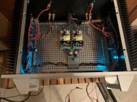
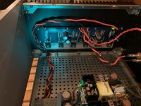
I am using two Mean Well EPS-65-24 SMPS for my Pass F4. There are three (in the picture) types of capacitors being used on the output of each module. A ceramic 22uF/50Vdc (RDEC71H226MWK1H03B) cap is soldered directly to the pins of the unit. Following that is a 5600uF/35Vdc electrolytic (EKYB350ELL562MMP1S) and a lower voltage film cap that I had left over from building passive crossovers (I don't remember the exact value or part number). Since the pictures I have added two (one on each rail) Panasonic 1200uF (EEU-FM1V122L) caps and the sound quality has appeared improved (no measurements yet). Some SMPS manufacturers will list the max capacitance load their units can handle, but Mean Well did not so I am starting small. A capacitance multiplier should be a great in this application!
Attachments
- Status
- This old topic is closed. If you want to reopen this topic, contact a moderator using the "Report Post" button.