Monsterreg V2.0 best to order 60uM boards.
Like the title says, this is an untested design for a 10A regulator for DHT tubes. So if you really have to glow a 833A this might be what you are after!
Ive used a LH0002 driver here, because it made sense to use that to isolate the LM358 from the horrendous capacitances of the power mosfets.
R1, the sense resistor needs to be dimensioned so that 1V means 150% of the nominal drop over this resistor, to account for the extra current needed during startup. so 10A means about 68mOhm in this position.
Given the current requirements you need a TO220 device in this position.
Suggested mosfet is : IXTH80N075L2. IXTH80N075L2 IXYS - Transistor: N-MOSFET | unipolar; 75V; 80A; 357W; TO247-3; 160ns | TME - Electronic components
I have not tested this design, and there are some tweaks im saving for the commercial product i'm developing.
Attachments


Last edited:
DIN41617 based boards for matching tubes.
I got something along those lines in my Dropbox somewhere, let me dig it out. Its a series of fixtures that can also be used for noise measurements. I designed those and still have a big box of prototypes somewhere.
They where based around some obscure 21P DIN41617 connector, and are all the same size. Ideal for anyone that is building a tube matcher.
Edit, i found the map, but its a bit of a mess right now.
Here's an example of the test board for EL84 matching jig, back from the time i was still etching my own boards. Like you might have guessed from the cathode resistor and bypass these are the cathode bias variety.
I would have to look up the connections, but these where made with remote sensing for the heaters in mind, to get the most accurate results. The noise measurement variety has coupling caps on the board that are connected to two pins, so you can measure the noise on four sections of dual triodes simultaneously.
thanks, 9 pin miniatures and octals....some sort of a screening bed for tubes that will find its way to a finally built amp...
I got something along those lines in my Dropbox somewhere, let me dig it out. Its a series of fixtures that can also be used for noise measurements. I designed those and still have a big box of prototypes somewhere.
They where based around some obscure 21P DIN41617 connector, and are all the same size. Ideal for anyone that is building a tube matcher.
Edit, i found the map, but its a bit of a mess right now.
Here's an example of the test board for EL84 matching jig, back from the time i was still etching my own boards. Like you might have guessed from the cathode resistor and bypass these are the cathode bias variety.
I would have to look up the connections, but these where made with remote sensing for the heaters in mind, to get the most accurate results. The noise measurement variety has coupling caps on the board that are connected to two pins, so you can measure the noise on four sections of dual triodes simultaneously.
Attachments

Last edited:
LM317(HV) EL34/KT88/6L6 tube maida MK2 single version.
I have boards available for this project, and can also supply parts.
These are ideal for feeding phono stages.
This is a simple tube based Maida-style regulator. Suggested IC is either LM317AHVT or TL783.
Heatsink is a SK129-38.
Cadjust 10uF is required for stability.
Please keep in mind that if you want to use this as a wide adjustment lab supply, that is possible if you run the pass tube with a floating G2 supply, and use a higher voltage regulator like the LM317AHVT or TL783*
*The TL783 needs minimum 10-15mA load current to regulate, so you need to add a 10M45S current sink to the output to keep the IC in regulation in case of low load operation. In that case you can get away with a triode EL34 up to about 500V input. Set the 10M45S to about 10mA and set the divider current to approx 3mA
Attachments


Last edited:
Dual PL36 based maida regulator
This is another tube based maida, just PL36 this time, this board may have issues, if you spot any on the plots, let me know and il upload fixed gerbers.
I have two partly built boards remaining from my previous lot, PM if you are interested.
These use the inexpensive PL36 tube, and with the right modifications the board is broadly applicable.
They use the Belton sockets, SK129 heatsinks. Don't forget to order 15mm M3 spacers to mount the sockets.
Cheers!
Attachments


Thanks for the encouragement,
This is an unfinished project, its a +-100V 20mA opamp buffer from a Jim Williams app note. This is interested for the people that want to build tube test equipment. Ive breadboarded the unit, and it works fine, BW is about 10Khz.
Dimensions are 2.5x2.5'' all holes and connectors are on a 2.54mm grid, so these boards align well with veroboard or experimenting PCB's.
If there is demand, i will finish the design, note that the circuit is missing/incorrect values, and some resistors are still 1206
Attachments


UX4 Type output, universal noval 9 pin driver amplifier
These boards are self-explanatory.
These use the expensive but excellent CMC UX4 sockets. 404 Not Found
Can use any Noval tube you like, RC coupled to the UX4 output.
Beware that these boards feature mirrored sockets, made for under chassis mounting.
PM if you need a custom version.
These boards are self-explanatory.
These use the expensive but excellent CMC UX4 sockets. 404 Not Found
Can use any Noval tube you like, RC coupled to the UX4 output.
Beware that these boards feature mirrored sockets, made for under chassis mounting.
PM if you need a custom version.
Attachments


Last edited:
ECC82 16GK6 amp
This is a board for 16GK6 outputs, a lesser known EL84 equivalent.
Boards are OK, they are playing for well over a year with a friend of mine.
Driver is a ECC82/12AU7 from the top of my head, but i might be wrong here.
Some values are missing, feel free to add these yourself, its a minor inconvenience.
Sockets are mirrored, made for under chassis mounting
Attachments


Mosfet SimpleA2driver board.
Mosfet source follower board, if i'm not mistaken this version has a 10M45S plate load for the driver tube and one connected to the bottom of the mosfet as a sink.
I vaguely remember there might be some mistake in this board, if you spot it, let me know and i will fix the mistake.
Mosfet source follower board, if i'm not mistaken this version has a 10M45S plate load for the driver tube and one connected to the bottom of the mosfet as a sink.
I vaguely remember there might be some mistake in this board, if you spot it, let me know and i will fix the mistake.
Attachments


Bias servo modules
These are modules for a bias servo for class A/AB amps.
Dimensions are exactly 2x2'' and the connectors and mounting holes are on a imperial grid, so these fit on veroboard.
These work great, but they have one requirement, that is that the power to the opamp needs to be interrupted until the tubes are warm. Otherwise the servo will try to upregulate cold tubes and given the slow time constant of the module this will inevitably lead to massive current draw.
I think you can get away with LM358 instead of that LT chip, provided you up the value of the decoupling caps on the resistor divider.
Edit, Ive also added the .LBR file for the footprint of the board.
Attachments


Last edited:

Great work and thanks for what your doing here for all of us diy people
Do you have anything for a phono pre amp in a tube ? Something that a newbie could build. Well some what if a newbie. Lol
I’d like to see something with the power supply and the pre amp side
Thanks
Carl
Do you have anything for a phono pre amp in a tube ? Something that a newbie could build. Well some what if a newbie. Lol
I’d like to see something with the power supply and the pre amp side
Thanks
Carl
Parallel ECC + EL84 fixture tube tester
This is a fixture for DIY tube testers/measurement setups. its a very simple board, that parallels the tubes, included are resistors against oscillation. Suggested for the anode EL84: 10R and 100R for everything else but G1 that is 1K or 2K2.
Ive built some testers that have sockets pre-wired for different tube types. I also have an Octal board somewhere in my extensive projects list.
Remember: The tube sockets are on a different side from the components. made for under chassis mounting.
Dimensions : 80x100mm from the top of my head.
Attachments


Tube tester anode and grid supply (mosfets)
The schematic for this board is from the project of a Dutch DIY enthusiast, its a board for the two high voltage supplies in a parametric tube tester. The schematic is not rocket science at all, and will function as it should.
Its just two mosfet source followers fed from a potentiometer that is in turn fed from a zener stack. P1, P2 and P3 mean pin1 pin2 and pin3 of the potentiometer.
Vout 0-250V, current can be set by the resistors.
R6 and R10 are the only hard to understand components in the supply, if you choose to populate these resistors you can have a crude but effective foldback limiting.
The other solution is just to use Mosfets that are tough to kill, and in TO220 there is little competition to the IXTP15N50L2, if you use these on a decently sized heat sink, there is little chance you can blow them up. IXTP15N50L2 IXYS - Transistor: N-MOSFET | unipolar; 500V; 15A; 300W; TO220-3; 570ns | TME - Electronic components
For best results its recommended to use a 100K 3W 10 turn pot for the voltage control.
Allthrough you CAN isolate the mosfets its better to screw them directly to the heatsink with some thermal grease, and isolate the heatsink on a piece of Phenolic board.
Attachments


Last edited:
Tube tester negative and fillament DC supplies.
These are the Negative control grid supply and the filament supply.
The control grid supply takes a +1.25V reference from a LM385-1.2. So it will regulate from 0 to about -30 volts. This supply is designed to operate from a 24VAC PCB transformer.
The Filament regulator can either be a LM338 or a LD1085 3A LDO regulator, but the latter needs 100uF output capacitance for stability.
The AC input of this supply depends on what you want to do with the tester. If you only want to do 6.3V or lower, 8VAC ~4A will suffice.
Diodes are SB560 and a generic small bridge rectifier of at least 100V 1A, reverse polarity diodes 1N4005-1N4007.
Attachments


GB Time delays plus protection boards.
With all the free stuff floating around i think i can get a pass at plugging my GB for a time delay with built in over current protection for the output tubes.
Heres the text from the GB, i've left out the financials.
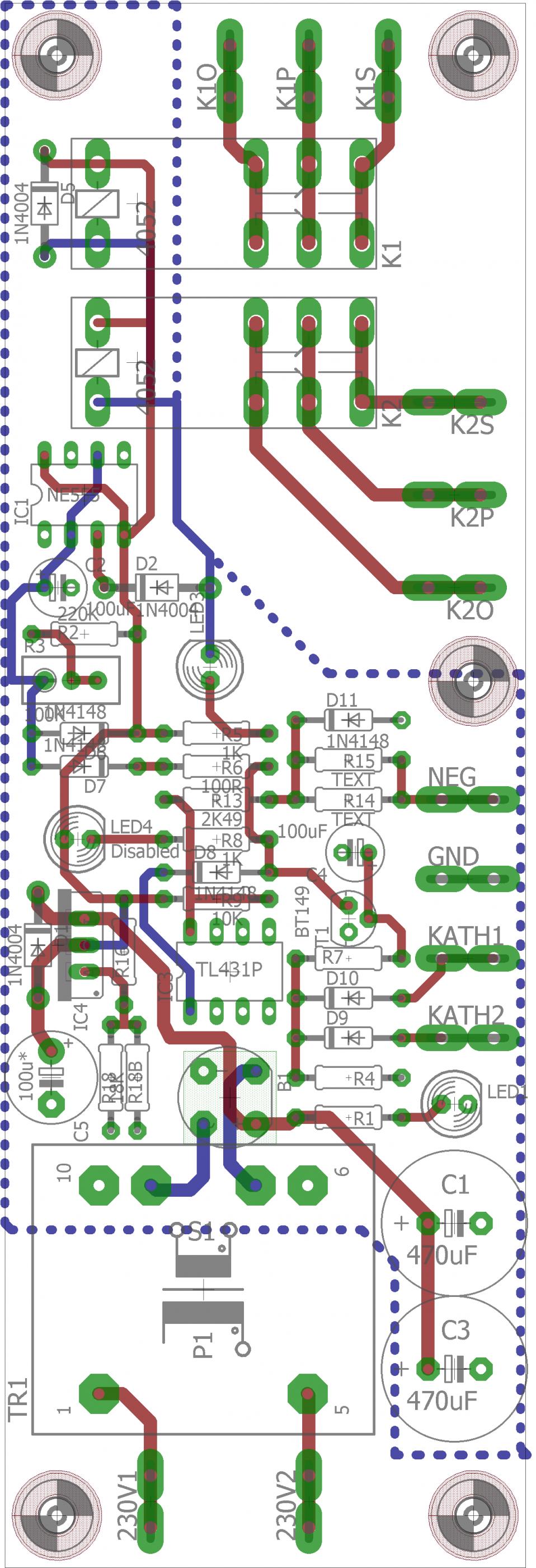
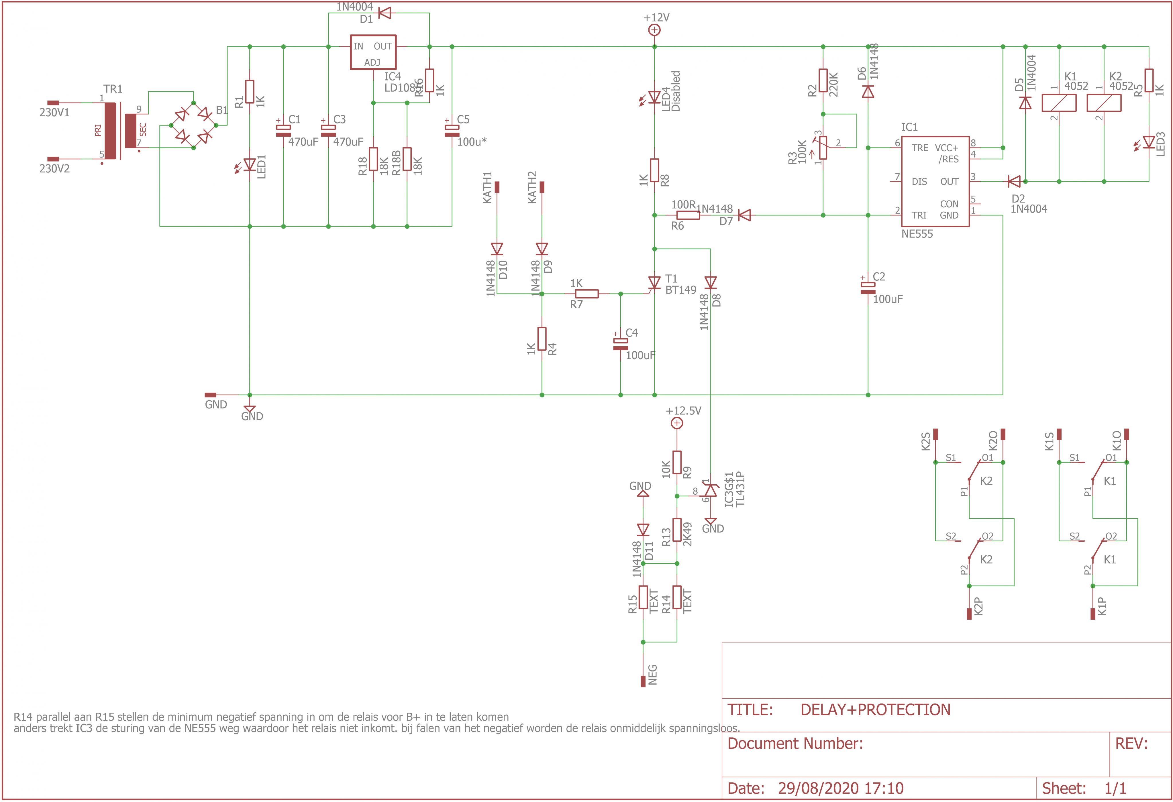
This is a board for a dual relay time delay with some extra protection feature for use in fixed bias tube amplifiers.
The supply of the boards consists of a 230V transformer, but if there is enough demand i'l make a version with a 115-115 primary transformer.
Included are two 12V coil relays that are driven directly by the 555 outputs. The 555 forms a simple time delay, that activates once the charge across the capacitor reaches 2/3VCC.
There is an on board thyristor that will trigger from a 1.0-1.3V signal from the cathodes of your output tubes, this means that with a 10R sense resistor in the cathode leads the circuit will trigger at 100-130mA. Once it triggers it will pull the input of the 555 low, disabling the output relays until the power is reset.
There is also an optional TL431 based protection circuit, that guards the bias supply, once the bias supply sags in enough, the reference pin of the 431 will be pulled high, and it will in turn discharge the timing capacitor as well. So if there is no bias there is no HV, but if the bias is enabled by means of the relays the module wont start. but like i said this part of the circuit is optional, and perhaps a nice addition if you plan on using a separate transformer for bias.
These would be ideal for example for class A amps with 845/211/GM70 that use a separate transformer for the high voltage and bias.
With all the free stuff floating around i think i can get a pass at plugging my GB for a time delay with built in over current protection for the output tubes.
Heres the text from the GB, i've left out the financials.
This is a board for a dual relay time delay with some extra protection feature for use in fixed bias tube amplifiers.
The supply of the boards consists of a 230V transformer, but if there is enough demand i'l make a version with a 115-115 primary transformer.
Included are two 12V coil relays that are driven directly by the 555 outputs. The 555 forms a simple time delay, that activates once the charge across the capacitor reaches 2/3VCC.
There is an on board thyristor that will trigger from a 1.0-1.3V signal from the cathodes of your output tubes, this means that with a 10R sense resistor in the cathode leads the circuit will trigger at 100-130mA. Once it triggers it will pull the input of the 555 low, disabling the output relays until the power is reset.
There is also an optional TL431 based protection circuit, that guards the bias supply, once the bias supply sags in enough, the reference pin of the 431 will be pulled high, and it will in turn discharge the timing capacitor as well. So if there is no bias there is no HV, but if the bias is enabled by means of the relays the module wont start. but like i said this part of the circuit is optional, and perhaps a nice addition if you plan on using a separate transformer for bias.
These would be ideal for example for class A amps with 845/211/GM70 that use a separate transformer for the high voltage and bias.
Last edited:
Fixture system continued 21P DIN41617
This was the fixture system i was telling Tony about,
I have fixtures for all ecc tubes, you can choose how you wire pin 4,5 and 9. I also made fixtures for EL84 and EL34 (Nearly every octal output)
You can choose anode and cathode resistors, so they can be also used for burn in.
Pin 5 and Pin 6 where reserved for remote sensing of the heater supply.
At the time i wanted to make a curve tracer that displayed ABS(IA1-IA2) on a scope, but too many projects. It was also to be suitable for noise measurements on tubes, therefore there are coupling caps from the anodes of the dual triodes.
If there is any need for fixtures like this from anyone, I can update the design. A fixture for 6SN7 was planned but never finished.
Attachments
-
 photo_2020-09-04_09-47-38.jpg240.8 KB · Views: 177
 -
 photo_2020-09-04_09-47-34.jpg259.7 KB · Views: 194
 -
 photo_2020-09-04_09-47-04.jpg256.8 KB · Views: 202
 -
 photo_2020-09-03_17-16-18.jpg288.6 KB · Views: 220
 -
 photo_2020-09-03_17-16-06.jpg305.1 KB · Views: 262
 -
 Fixture system schematic.png51.7 KB · Views: 288
Last edited:
LM317/LD1085 PCB
you're welcome.
Here's another one for the tally, these are 49x100mm PCB's for mounting against a top plate or heatsink.
Can be used with TL783 LM317 LD1085 and the list goes on, check the respective datasheets about output capacitor requirements. LD1085 needs 100uF on the output for stability.
Two in a panel of 100x100mm.
Attachments


- Home
- Amplifiers
- Tubes / Valves
- V4lve lover's free Gerbers thread