I bought a used PVA-7, knowing that it might have some problems. Powered up on the DBT, 60w, 75w, 150w - no issues. Checked for DC on all the outputs - none were higher than 20mV. So I moved to testing with an 8r dummy load resistors, still on DBT with no issues. Took the amp off the DBT and tested with 500Hz and 1000Hz sine waves into the 8r dummy loads up to about 50% power - again no issues.
Here is where it gets weird - connected the amplifier to some low-grade speakers for initial test. At low volumes on sine wave or music (~<1w) it sounds okay and will play. As soon as you turn up the volume on sine wave or music to 2-3w, the bias jumps up from 15mV to close to 1V and the 10r output (zobel) resistor heats up and the amplifier shuts down, protection circuit kicks in This oscillation/overheating takes about 3-5 seconds to kick-in the protection, depending on how much you turn up the volume.
I tried the same test with only the faulty channels (2 channels on a single heatsink) on DBT and will play fine up to 27Vac (max preamp volume) on the speaker outputs as long as it's playing into an 8r dummy load. As soon as I connect my speakers (~6.7r nominal load) it will cut out at around 75% volume and you can see the current ramp-up in the DBT. As the DBT lights up, so does the 10r resistor on the output.
Final test was to try each channel separately and it appears it is only on one channel, I can hook up the other channel to the speaker and play as loud as I want with no issue. I can connect to the 8r dummy load on faulty channel and still plays up to 75% before protection. But a speaker on the faulty channel or both channels hooked up to speakers and it shuts down quickly.
Amplifier board: I have tested all TO-92, pre-drivers, drivers and outputs to the working channel and everything checks out. Measured every resistor and diode going bad board to good board and they all measure within 1-2%. Output BJTs measure good and no DC on the output - so I'm at a loss to why the amplifier is oscillating.
Also - nothing except a 2N5551 has been changed in the relay circuit. Measured a little low on Hfe, so I changed it out. Everything else, including solder joints all look original - not been touched.
Can this be capacitors? I know typically you would add, change or revise capacitors in the circuit to kill the oscillation, but since this is totally stock, could it be a bad capacitor in the circuit causing the oscillation?
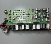
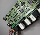
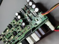
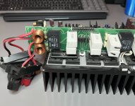
Attachments
@huggygood good suggestion, I always assume they won't help, or there would be schematics floating around, but I sent there tech team an email explaining the issue and requested a schematic or some insight if they have encountered this issue previously.
I fixed another one of these earlier this year and it was very straight forward faults - DC on the offset (bad channel outputs and a few resistors), the other channel had a bad 2N5551 in the protection circuit, not allowing it to come out of stand-by. Both fixes were quite simple and showed up from a comparison of the Transistors with working channel. That's what is so perplexing on this issue - everything matches to a known/tested working channel, but still oscillates.
I will keep my fingers crossed that Anthem provides something that might help me. Otherwise, no choice but to shotgun some parts and see if a blind squirrel can find a nut! Luckily I have most parts from the repair earlier this year.
TO-92s - 2n3904, 2n3906, 2sc3495 replaced with 2sc1845 (input pair), mpsa56, 2n5551
TO-220 (pre-driver and driver)- MJE340, MJE350, MJE15032, MJE15033
TO-264 (outputs) - 2sc3281 and 2sa1302)

Well, as expected Anthem does not provide schematics or offer repair assistance directly to owners - against Company policy. They did offer me to send it to them, and quoted the repair could be as low as $160 (+ shipping to and from).
I guess it's time to re-cap the electrolytics (hoping a few test way out of spec) and re-test. Then resort to replacing small fil capacitors, starting on the output board and supply filtering. I'm going to hold off on transistors, since they all test fine and DMM and voltages seem correct.
Any thoughts on this "shot-gun" approach?
Well - I changed out (8) capacitors from the input to the bias pots (C1, C11, C26 and C35 all 16v 330uF) (C16, C38 and C42 all 35V 22uF) and finally C41 (63V 22uF), Tested the old caps and the 16V 330uF tested within tolerance, but the others were in the 8-10% Vloss and 10-15r ESR, so needed to be changed, but did not fix the amplifier. Didn't bother changing the filter caps on the boards, since they don't show any signs of stress on the caps or board area.
Seems to be either leakage on input pair, (2SC3495) or leakage on the bias transistors (MJE340/350). Only thinking this because it will play music at low volumes fine, but only when additional current is drawn, does it seem to oscillate. Open to suggestions?
Seems to be either leakage on input pair, (2SC3495) or leakage on the bias transistors (MJE340/350). Only thinking this because it will play music at low volumes fine, but only when additional current is drawn, does it seem to oscillate. Open to suggestions?
You should be able to capture it by setting the trigger level so something reasonably high (since oscillation is likely to be high amplitude) and using the single-shot mode on the scope. Some experimentation will be required to get the best waveform display. Shouldn't be any issue connecting the scope across the loudspeaker, just make sure the ground lead is on the minus side and that the volts/div is high to begin with until you know what your'e dealing with. You could also set the timebase really slow so that there's no way you can miss the event. That way you can get to see the amplitude and then use more appropriate volts/div and trigger settings on the next run.
Interesting testing after changing caps, now I can play either channel separately through speakers with no issues, but as soon as I connect both inputs the protection kicks in.
I think my next step is changing the remaining 12x63v 330uf filter caps, since I have them and the are fairly easy to change.
O-scope is still packed up from our move, so trying a few easy things before locating box and somewhat blindly taking measurements.
I think my next step is changing the remaining 12x63v 330uf filter caps, since I have them and the are fairly easy to change.
O-scope is still packed up from our move, so trying a few easy things before locating box and somewhat blindly taking measurements.
That's curious!Either input by itself and I can play music as loud as my iPhone volume will go, but as soon as I plug in both inputs (with or without) music playing it goes into protection
If you join the ground the shells of the two channels to each other, is protection triggered? Same question, joining signal inputs? Is there a DC voltage difference shell-to-shell or signal-to-signal?
Have you tested the amp with another cable and another signal source?I can play music as loud as my iPhone volume will go, but as soon as I plug in both inputs (with or without) music playing it goes into protection
Well - replaced the remaining 12 Electrolytic Caps (all 63V 330uF), and the old ones all tested within spec (1-1.5% Vloss, and 0.4-0.6r ESR, right around 315uF). But they have not been replaced before, or the person that did it is way better at it than I am.
Same issue - I can play music full volume from my iPhone into a Single Input and Speaker - but as soon as I have both Inputs connected and playing music it goes into protection. Looking at the bias, it almost immediately shoots up to 350mV, from ~12mV and would probably keep climbing if the protection didn't kick in and turn the power off.
I have never had this issue before, so I am quite stumped why the input would be the impetus for the issue - not load music or sine wave causing excess current draw?
I also monitored the pre-drivers (MJE340/350) and both channels act the same while playing music - collector hovers right around 1.1-1.2v and the PNP pre-driver measure within 1-2% but negative - all fluctuating the same, as the volume increases. Then (if I connect both inputs) protection kicks in, all voltage go away and then re-start and climb until protection.
This is the same with the Drivers (MJE15032/33) both channels measure similarly and fluctuate within the same range. I also checked the 2N3904's on the heatsink - bias tracking transistors. They act the same way, very stable until the protection kicks in.
Open to any and all suggestions - glad to take more pictures or start a spreadsheet with voltages?
Yes originally tested with an Outlaw 976 pre-amp, with Optical input (from PC) to pre-amp, then RCA to the amp channel(s) one at a time. Since then, I have been testing with an iPhone, with a lightning to RCA cable so there was not additional AC interaction possible. I have also tried tests with sine waves and music and it seems to show a problem when I connect both inputs.Have you tested the amp with another cable and another signal source?
- Home
- Amplifiers
- Solid State
- Anthem PVA-7 - Strange Oscillation