https://share.icloud.com/photos/0a3eq9YUx9tV4iAmI4-ycVxqQ
https://share.icloud.com/photos/008E3C5JVOYPHO_hEb-1kAXDQ
Here are two videos of worst channel, reminder this is not the channel I replaced caps on but this was how it first behaved until I changed Caps.
Only difference is that the repaired channel issue was resolved with adding clear tape around the RCA to keep the plug sleeve from contacting the chassis, again only one channel has this issue as seen in the videos, other channel no amount of pushing, twisting causes protection.
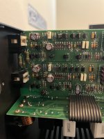
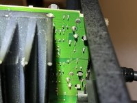
Could you post a closer photo of the older amp input stage area (near the RCA socket?so I could take a few pictures
Also from the other side of the board.
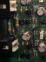
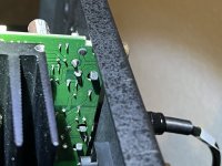
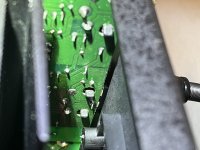
Some solderings look like cold joints from these photos but resolution is not good enough.
Best I could get since HS is in the way of back of board. Thanks for looking.
I tried to get hi-res, so let me know if you have issues viewing and I can downgrade the resolution.
Reminder: AMP 1 (bottom RCA) is the culprit on this amp board
I tried to get hi-res, so let me know if you have issues viewing and I can downgrade the resolution.
Reminder: AMP 1 (bottom RCA) is the culprit on this amp board
Attachments
Last edited:
+1Some solderings look like cold joints from these photos
Thanks for looking guys - I will pull out the board and go over as many joints as I can with the soldering iron and fresh solder (wouldn't that be great if that was the only problem??!!!). Sick kid yesterday, so I didn't get to do anything on the amp. Maybe today will be better - less work, more hobby!!!
I touched up all the solder joints on the top of the board and as many I could get to on the bottom, especially the RCA connectors. On the board that couldn't have both RCAs connected at the same time or I could force into protection by manipulating the plug.
Interesting result - still goes into protection with both inputs are connected - however, now I am unable to force it into protection by pushing the RCA fully in, or manipulating the plug.
So, I'm hoping this means that
- touching up the soldering will fix the fully seating and manipulating of the PCA problem
- replacing the 4 lower value capacitors (C16, C38 and C42 all 35V 22uF) and C41 (63V 22uF) will fix both inputs connected issue
Going to touch up the soldering on the board I previously replaced all the caps on, and still has the fully seating and manipulating RCA issue. I may be optimistic but this seems like it is progressing, albeit slowly.
My optimism has turned to despair... I replaced the 4 smaller caps (C16, C38 and C42 all 35V 22uF) and C41 (63V 22uF) on the channel I re-flowed solder on all joints. As part of the cap replacement I had to remove the board and was able to make sure all the joints were reheated and looked solid.
reinstalled and no change - still goes into protection as soon as you hook-up second pair of speakers.
Insult to injury... I reinstalled what was the working board (channel 6/7) and now it has the same symptoms. Fine with one pair of speakers (channel) playing, but as soon as second pair of speakers are connected, it goes into protection.
But, if I connected the bottom PCB speaker ground to chassis ground with a jumper (tried numerous place, but only works connected to the speaker ground for the lower RCA, amp #1), both channels play fine and listened to it this way for ~30 mins or more. No overheating heating, no sound issues.
I also tried to capture the protection behavior on my O-Scope, but it's too fast for the scope (or something, maybe me), because the signal is there and as soon as I connect the second RCA the scope trace/screen goes blank and doesn't come back until it come out of protection - then cycles until I unhook the RCA/speaker or turn off the amplifier. At no time during this cycling can I see/capture the sine wave again.
This seems to prove that it is losing ground somewhere (seems to point to lower amp channel), but I have checked continuity and resistance for all grounds - such as barrel of the RCA, the speaker grounds and the PSU ground (at both the PSU board and the plug from the PSU to the amp board) and I get continuity, around 0.4-ohms.
I was going to pull out the PSU board but there should not be a ground connection to the speaker ground here? I'll admit I'm getting frustrated and confused as to how there is an issue without any transistors, caps, resistors, diodes seemingly bad and all transistor voltages seemingly making sense.
I am at a loss of what to even try next? I guess I could try one of these older channels in the newer amp/PSU - nothing else connected and see if the symptoms go away, or follow the amp channel?
Anthem did brag about their ALM (automatic load monitoring) circuit mighty capability in protecting the amp.
Without a schematic diagram the troubleshooting would be much like fumbling in the dark.
I would go ahead and trace out a schematic by reverse-engineer it.
Otherwise, while using a conservative wattage dim-bulb tester, by disabling the protection may give you chances of having the amp stay in malfunction mode long enough for scope capture.
After fighting all these days and ending up with little positive development, perhaps leave it aside for a few days, have some good meal, good drink, good sleep, cool down a bit before further efforts?
By the way, from the pictures you posted so far, the ground connection on the output stage PCB seems to be, taking the speaker negative wire soldering joint as reference,
1. amp 1 and amp 2 speaker negative wires are not tied together immediately where they get soldered on the PCB.
2. there are two ground traces, one thick, one thin, coming off each of the speaker negative wire solder joints. The thick ones would travel the length of the PCB and join each other at the power inlet connector.
3. the thin trace coming off the speaker negative wire solder joint would go to the flat cable, in turn, go on to the respective front end of the amp.

I am trying to take my time, so I don't make anything worse.
I have been doing all this testing with a 150w DBT and afraid to take it off, because when it goes into protection it is drawing some significant current, as the bulb lights up 30-40% before the protection kicks in.
It is strange that working channels have gotten worse and the only variable is the DBT??? I wouldn't think two channels only, running through 150w bulb would cause enough current draw to trigger any protection. It's the biggest bulb I have.
I could have made myself a bit more clear.
What prevented you from being able to capture waveforms on a scope was the amps own protection kicking in and shutting the amp down before you had a chance of doing it.
What I was proposing is to disable that protection, by, for instance, disconnecting a relay coil.
What I meant by "using a conservative wattage dim-bulb tester" was to use a small wattage bulb in the DBT. Instead of a 150W bulb, perhaps try a 60W one, so as to prevent overcurrent damage while the amp's own protection is out of action.
- Home
- Amplifiers
- Solid State
- Anthem PVA-7 - Strange Oscillation