Hi, I think you could do away with the output buffers all together and just use an RC filter and a second resistor to make a balanced out with the PCM5102a. For the 12VDC input polarity protection, could you not just use a series diode? For the input ADC, there is the PCM1840, differential inputs with a minimum of components and tdm mode. Down side is that has a 1st order low cut filter built in that is tied to the sample rate, ie 12Hz on a 48KHz clock, 24Hz on a 96KHz clock.
Dear Pit good morning.
Great new about the eigh balanced outputs. No problem about the wires..That's not a problem.
I've one small request about this project..could you add please an AES/EBU In-OUT in capability?
Using the TDM interface..would be possible to carry on the left...or right channel to a second OCTAVIA Card...?
Many Many thanks in advance.
Maurizio
Hi TNT.I think that having a board that has the player, EQ possibility (Camilla) and DAC for 8 channels at a reasonably price would be great. Balanced out is of course very attractive. See to that Wifi could be switch off completely if one don't need that.
//
This would be a very attractive project for all the camilla DSP users.
Maybe Pit will have time in the next future to develope something like this...but i think we should contribute about the costs..components..pcbs prototypes...etc etc..
Member
Joined 2018
Hi Guys,
ADAU1451/1466 does not have the 8ch AES/EBU digital I/O serializer. Additionally, we need to switch the impedance 75 ohms/110 ohms if we add AES/EBU interface capability. Those things make a complicated design board. I guess TDM or ADAT(I8S) interface will be applicable if you need to transfer 8 channels with one cable. (You can download my design which is named "freeDSPx-ADAT-IO-x4" a 48kHz 23bit x 8ch optical interface boards) According to those reasons the FreeDSP OCTAVIA will not be able to implement those features...
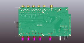
Now I complete the artwork of FreeDSP OCTAVIA version 0.1
Thanks, Subsonics-San, the reverse voltage protection feature had been implemented.
A very tight parts layout is needed, so we'd better use PCBA service when building this board.
The attached data will be committed to FreeDSP Git-Hub soon...
CyberPit
ADAU1451/1466 does not have the 8ch AES/EBU digital I/O serializer. Additionally, we need to switch the impedance 75 ohms/110 ohms if we add AES/EBU interface capability. Those things make a complicated design board. I guess TDM or ADAT(I8S) interface will be applicable if you need to transfer 8 channels with one cable. (You can download my design which is named "freeDSPx-ADAT-IO-x4" a 48kHz 23bit x 8ch optical interface boards) According to those reasons the FreeDSP OCTAVIA will not be able to implement those features...
Now I complete the artwork of FreeDSP OCTAVIA version 0.1
Thanks, Subsonics-San, the reverse voltage protection feature had been implemented.
A very tight parts layout is needed, so we'd better use PCBA service when building this board.
The attached data will be committed to FreeDSP Git-Hub soon...
CyberPit
Attachments
-
 FreeDSP_OCTAVIA_ParseView.jpg282.2 KB · Views: 218
 -
 FreeDSP_OCTAVIA_TopView.jpg294.2 KB · Views: 204
 -
 FreeDSP_OCTAVIA_BottomView.jpg192.6 KB · Views: 167
 -
 FreeDSP_OCTAVIA_PCB-Top.jpg388.9 KB · Views: 184
 -
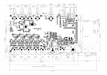 FreeDSP_OCTAVIA_BoardDimensions.png146.1 KB · Views: 226
 -
FreeDSP_OCTAVIA_Schematic.pdf510.3 KB · Views: 150
AES/EBU is pro - is this needed really. I'd say no. Board look impressive - congrats!
Talking about ADAT, I have a RME Digiface Toslink. It has 4 opto out and can do ADAT i.e. it can output 32 discrete channels - but - its hard to find ADAT compatible DACs. I would like to have a board that could do 4 toslink opto in (ADAT) -> 16 opto (2ch) toslink out... to be used with an ordinary DAC (max 48ksps) does such a board exist?

Sorry for OT..")
//
Talking about ADAT, I have a RME Digiface Toslink. It has 4 opto out and can do ADAT i.e. it can output 32 discrete channels - but - its hard to find ADAT compatible DACs. I would like to have a board that could do 4 toslink opto in (ADAT) -> 16 opto (2ch) toslink out... to be used with an ordinary DAC (max 48ksps) does such a board exist?
Sorry for OT..
//
Member
Joined 2018
Hi TNT-San,
Well, it's hard to find an ADAT-compatible DAC. freeDSPx-ADAT-IO-x4 is using a tricky design for I8S format data transfer via the ADAT light pipe. Originally, an ADAT receiver device V1402 is designed for the left justified format DAC. It needs a one-bit data delay (such as HC74...) to reform the format to I2S.
It's easy to design but hard to find off-the-shelf products.
Let's DIY!
CyberPit
Yes - but I dont have the knowledge to do it myself but I would happily cheer on (in an other thread) and do a build if I could master it. Think about it CyberPit-san! :-D It would be a step closer to my 12+12 ch segmented bending wave corner line source, delayed to behave like a point source...
//
//
CyperPit it looks amazing
Great work.
The pcb is 4 layers, right: signal, GND, VCC, Signal?
One question: I fully understand the need for the OPA1632 for balanced output, but they are not really needed for single line. Do you expect the buffering will have a positive performance improvement even though?
As for digital signals, I guess most optimal would be Dante ... routing whatever to wherever. At least for multi channel use. I'm designing towards my home theater and would have loved to be able to go from the processor all digital. JBL has introduced the SDP-58, which has Dante output, but it is so much out of my reach money wise
This way you can skip one DAC - ADC step and you are also getting rid of all those input and output connectors, drivers etc. ... whish someone would make a cheaper alternative, as Dante is expensive all the way through ... but really smart
For going full active at the speaker, I guess you could have TOS-Link into both speakers (stereo into both) and then at the speaker chose if it the left or right channel with a small switch or something, telling the DSP which stream to use.
Member
Joined 2018
Hi TNT-San,
12+12 ch segmented bending wave corner line source project is interesting from the point of view Point-Source.
It does not need much effort to inherit the design ADAT to the I8S board from the freeDSPx-ADAT-IO-x4.
If you make a wishing thread for that project, Maybe I can support the hardware design.
Hi Baldin-San,
The board is designed in only two layers. So it's easy to order and build. (But quite hard work for design ...)
This board can use for four variations. Of course, single-end outputs are available as BASIC version.
Please have a look at the attached schematic part...
This is looking amazing CyberPit, thankyou for sharing your expertise with the community!
I wish I had more skill and knowledge to add to the development but my two use cases for such a product are:
1.Active speaker crossover and DSP so the toslink to each speaker as suggested above by Baldin would work for me too. Balanced I/O are on my wishlist also.
2. raspberry pi streamer/pre all in one unit with analog inputs to output to active amplification. I use a lot of raspberry pi in my home at the moment - picore player; hifiberryOS and Volumio but I'm also a fan of Moode Audio. I'd like to start playing with camillaDSP.
Your pace of development is impressive! Keep up the great work!
Member
Joined 2018
Hello Guys
I just estimated PCBA cost on JLPCB page. (SMT only, exclude hand mount parts)
I need to fix axis offsets some. But almost SMD devices are included.
2 of 5 boards' PCBA costs $211.06 (Shipping cost not included) --> $106 each
5 of 5 boards' PCBA costs $389.95 (Shipping cost not included) --> $80 each
10 of 10 boards' PCBA costs $699.36 (Shipping cost not included) -->$70 each
One-gate logic inverter and SPI-EEPROM were not in stock, so I estimated 32Kx8 devices instead of 25LC1024.
It's difficult to find SPI EEPROMs today, but I2C EEPROMs are not. So now I considering using I2C EEPROM for the ADAU1452 DSP self boot...
CyberPit
Hi CyperPit-San
JLCPCB have the M95256-RMN6TP on stock, (853 pcs at 1 $ each) which is a SI device ... but maybe that is also what you have found, and hense your comment on 32kbx8.
I have my eyes on CAT24C512WI-GT3 which is a I2C 512 kb chip.
From what I have read probably both 256 and 512 kb will be enough .... but I also see the reference design using a 1Mb chip .... so who knows .... of course depends on the signal processing you want to do ..
Member
Joined 2018
Hi Baldin-San,
Well, the ADAU1452 can run almost 8 times the processing steps of ADAU1701. So the 8 times capacity of EEPROM size might make sense if fully used. Also, the SPI connection had been chosen for the advantage of its speed.(Not sure, just my guess)
From the point of view of the software side. If I change the USBi/TCPi header side connection to I2C, there will be many reusable software resources that come from the FreeDSP Aurora repository. Losing a high-speed transfer capability from SigmaStudio will not be a big matter in most of the use cases if the self-boot path is using SPI.
I would like to hear the opinions and make a little time to rethink the choice of USBi/TCPi connection interface type...
CyberPit
Hi CyberPit-San
I was thinking to find out how much EEPROM space I'm using in my ADAU1701 design for comparison.
Not really sure where to find the information, but I would guess compiler_output.txt file gives the answer:
################## Summary ########################
(Note: Estimates are based on a 48 kHz sample rate)
Number of instructions used (out of a possible 1024 ) = 709
Data RAM used (out of a possible 2048 ) = 351
Parameter RAM used (out of a possible 1024 ) = 154
Files written:
program_data.dat - load file for downloading code using ADI loader
hex_program_data.dat - load file for downloading code using microcontroller
spi_params.dat - file of parameter values for each instance, used by gen_spi program to make download file
spi_map.dat - Parameter RAM locations for each schematic instance
trap.dat - lists the values to enter in the trap registers to output a signal to the data-capture output pin.
So I'm using 70% of the available instructions cycles.
I would guess the hex_program_data.dat is the raw data to be loaded into EEPROM, This file is 32kbyte ~ 8x32 = 256kb so a full EEPROM image.
Looking into the file there is a lot of zeros at the end, meaning that not all is used.
I dumped it into an excel sheet, and out of 1024 lines, 709 contains data (same goes for program_data.dat) .... hmmmm I had actually thought there was more code for setting up the DSP, communication, parameter data or something, but it seems to relate directly to number of single cycle instructions.
So if the word length is the same for ADAU1452 as for ADAU1701, then yes, well need 8 time 265 kb = 2 Mb!!!!
Can that really be correct??
Ok, page 96 of the data sheet says https://www.analog.com/media/en/technical-documentation/data-sheets/ADAU1452_1451_1450.pdf
the ADAU1452 has:
40 kWord (32 bit) = 1,28 Mb of data RAM
8 kWord (32 bit) = 256 kb of RAM
So 1.5Mb in total ... so the EEPROM should have this size as minimum to fully utilize the potential.
A not is that for self boot using SPI, only one EEPROM can be used as I read it on page 54 top. For I2C you can use different addresses to cater for multiple EEPROM chips.
So in general 1Mb is not too big at all
And writing this amount of data of course also takes a bit of time using the 100kHz I2C interface ... probably why you would want to stick to SPI (1MHz)
Mouser have an 4Mb SPI 25CSM04-I/SN at 3,5€ in a SOIC-8 case which is easy to hand solder
Last edited:
- Home
- Source & Line
- Digital Line Level
- FreeDSP OCTAVIA