
An unbal distortion box, or desecrating Papa's Good Works
I've had in mind for a while now to make a line transformer based "unbal" to be able to drive some of my Pass amps that can take balanced inputs from single-ended sources. A while back I flailed around trying to make my 1:8 turns ratio Electra-Print PVA-2n's transformers generate balanced output, but they lack center taps, and so I gave up due to weird phase shifting issues I'd see on the output, depending on where the volume control was placed. I'd used a pair of Edcor 1:2 turns ratio 1/2 watt WSM 600R:2400R line matching trafos in various things, but came out convinced they needed a current buffer of some kind to drive them properly. Enter Papa's H2 V2. A simple source follower JFET buffer, cheap & available, maybe it would work to drive the Edcors?
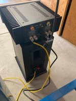
So I bought one and built it up with scavenged & junk box parts, to include a switching wall wart rated at 12V that seems to want to deliver over 13V. I didn't have the right pots or even 33R resistors to properly set the JFET bias, so I hacked an operating point with some 68R resistors I had. At 11.4V at T2 it's about a volt higher than the sweet spot of 10.57V written on the diyaudiostore envelope, so less 2nd order harmonics most likely. Fine.
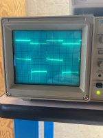
Anyway I wired it & the Edcors up on the bench & hooked it up to a signal source and scope. At about 1.3V p-p and higher on the input, the negative half of a sine wave starts to get rounded, with some interesting ringing in the smushed trough showing up at 1.7V p-p input and above (sorry, no pictures). With a square wave there is tons of ringing at nearly any frequency. A 220pf cap in series with a pot on the Edcors secondary helped a little, by twiddling with it I landed on a value of about 4k7 which snubbed some of the ringing. I wired it in permanently as an RC snubber across the secondaries.
Listening to a single channel in bridged mono on an ACA driving a Klipsch bookshelf and the thing sounds pretty amazing. A lot of the harshness I associate with some of my AirPlay digital sources was reduced, and the bass was stupid good. There's trafo hum but as this unit isn't in a grounded case yet, I'm hopeful that can be mitigated somewhat. I need to put this in a case!
I've had in mind for a while now to make a line transformer based "unbal" to be able to drive some of my Pass amps that can take balanced inputs from single-ended sources. A while back I flailed around trying to make my 1:8 turns ratio Electra-Print PVA-2n's transformers generate balanced output, but they lack center taps, and so I gave up due to weird phase shifting issues I'd see on the output, depending on where the volume control was placed. I'd used a pair of Edcor 1:2 turns ratio 1/2 watt WSM 600R:2400R line matching trafos in various things, but came out convinced they needed a current buffer of some kind to drive them properly. Enter Papa's H2 V2. A simple source follower JFET buffer, cheap & available, maybe it would work to drive the Edcors?
So I bought one and built it up with scavenged & junk box parts, to include a switching wall wart rated at 12V that seems to want to deliver over 13V. I didn't have the right pots or even 33R resistors to properly set the JFET bias, so I hacked an operating point with some 68R resistors I had. At 11.4V at T2 it's about a volt higher than the sweet spot of 10.57V written on the diyaudiostore envelope, so less 2nd order harmonics most likely. Fine.
Anyway I wired it & the Edcors up on the bench & hooked it up to a signal source and scope. At about 1.3V p-p and higher on the input, the negative half of a sine wave starts to get rounded, with some interesting ringing in the smushed trough showing up at 1.7V p-p input and above (sorry, no pictures). With a square wave there is tons of ringing at nearly any frequency. A 220pf cap in series with a pot on the Edcors secondary helped a little, by twiddling with it I landed on a value of about 4k7 which snubbed some of the ringing. I wired it in permanently as an RC snubber across the secondaries.
Listening to a single channel in bridged mono on an ACA driving a Klipsch bookshelf and the thing sounds pretty amazing. A lot of the harshness I associate with some of my AirPlay digital sources was reduced, and the bass was stupid good. There's trafo hum but as this unit isn't in a grounded case yet, I'm hopeful that can be mitigated somewhat. I need to put this in a case!
Attachments


I think this needs a buffer or source follower (an extra stage) to get a low output impedance - the output impedance from the drain is simply too high. Driving the transformers in other circuits is mostly done with a 2SK170/2SJ74 buffers or similar.maybe Papa's H2 V2 would work to drive the Edcors 2:1?
And then - Afterwards realign your Zobel.
-a combo of a BJT and jFET, is also viable here to get a low impedance. I expect any electrolytic >>10µF will work on the output.
M2x offers eight different circuit designs (field swappable!) for driving an Edcor interstage transformer, from a high impedance input.
Studying their designs might provide design inspiration, when creating a buffering interface between H2 and and Edcor transformer. Forum Search finds them easily.
- JFET + BJT follower ("Mountain View")
- Opamp unity gain ("Tucson")
- 2SK170 + 2SJ74 push pull JFET follower ("Ishikawa")
- BJT diamond buffer ("Austin")
- Opamp plus 200 MHz video cable driver in a single negative feedback loop ("Norwood")
- JFET + BJT transconductance amplifier ("IPS6")
- Supply bootstrapping using BJTs, applied to opamp ("IPS7")
- Wild bronco AD797 opamp with input compensation and resonance damping ("Cedarburg")
Studying their designs might provide design inspiration, when creating a buffering interface between H2 and and Edcor transformer. Forum Search finds them easily.
Thanks both for the feedback. I wasn't aware that a common source topology would have a too-high output impedance to drive a transformer. Also I didn't mention, but after a while the square wave output at the transformer secondary would start to curve down after the ringing pulse and not really follow the square wave pattern anymore- not sure what this was but it's as if the core wasn't responding to the input pulses so I suspect DC was leaking in and saturating the core. Perhaps too small a coupling cap.
It appears the M2X cards are dual rail, which is unfortunate as I was hoping to use just a single cheap wall wart, not two in series or a dedicated power supply. But there are some simple and interesting ones like IPS6 and Mountain View that as you say, are inspiring. I have two LSJ74 JFETs I got as a gift from Linear Systems at Burning Amp, and a small pile of J111s and J113's; maybe these can be matched up. Maybe a differential pair topology is in order, but the ones I can recall tend to use a dual rail like the M2X cards.
Anyway, I don't want to clog up this thread as it was meant to be the H2 V2 build thread. Thanks again.
Hi!
I need help with finding right J113. I have measured 10 pcs J113 what I ordered and they vary Vp 1,4-1,9 volts and Idss 12,5mA - 20mA. Can anybody provide me right J113 JFETs or to find another JFETs that are more in specs and in right range like 2sk209 or JFE2140 etc? @Nelson Pass
I need help with finding right J113. I have measured 10 pcs J113 what I ordered and they vary Vp 1,4-1,9 volts and Idss 12,5mA - 20mA. Can anybody provide me right J113 JFETs or to find another JFETs that are more in specs and in right range like 2sk209 or JFE2140 etc? @Nelson Pass
I made pcb for this H2 v2 and I do not get it work. No sound when I plug my laptop audio out to input and H2 output to receiver amp. I am using J113 vp 1.8.
Whats wrong? T2 voltage 10,5, T1 voltage 6,6. Is this J113 vp to low and thats why not working or at least I should get some music out? I can increase input DC voltage up to 20 volts if needed.
What I am doing wrong? Please help.
Whats wrong? T2 voltage 10,5, T1 voltage 6,6. Is this J113 vp to low and thats why not working or at least I should get some music out? I can increase input DC voltage up to 20 volts if needed.
What I am doing wrong? Please help.
@elwood625 This is the picture what I have built. I made this pcb to test different JFET-s as you can see. What have to be the input signal level mV-s to work? Is it ok to feed this with audio from laptop headphone output to receiver CD input? I could not get any sound out of it.

R18 and R20 are for connection and 0 R. U10 and U11 are for switching different input +9db and unity gain. U16 is for JFE2140. J1 and J2 are for J113. P1, P2, U17 and U18 are connected with a wire on the back of pcb.

Help is needed to get this to work.
R18 and R20 are for connection and 0 R. U10 and U11 are for switching different input +9db and unity gain. U16 is for JFE2140. J1 and J2 are for J113. P1, P2, U17 and U18 are connected with a wire on the back of pcb.
Help is needed to get this to work.
@elwood625 I made the changes and connected RP1 and RP2 wiper to the lower pin. Input 12v, TP2 has voltage 10,47V and TP1 6,47V. Still no sound. Audio input 0,35 V ac and output 1 V measured with multimeter. Audio is from laptop headphone out. It get kind a hum noise but not any sound.
What could be the problem?
What could be the problem?
How disappointing, I thought for sure that would fix it.What could be the problem?
I took some measurements on mine which I built for unity gain, so R1 = 22K & R2 = 10K.
So with 0.35 VAC on the input, the Gate of the JFET is 0.109 VAC.
The DC voltages I measured are:
With 12.02 VDC input, T2 = 10.61 V and T1 = 4.28 V.
The DC voltage between R6 and P1 is 10.61 V.
The DC voltage between C2+ and P1 is 10.61 V (same as T2).
Try a different C1 (10uF) and J113.
I finally built my H2 V2 a few weeks ago. Most important deviations were a 10uF Elna Silmic II for C1, panel mounted 100R 25 turn pots (3590S-2-101L), 2 panel mounted 4 digit voltmeters and a 25k ALPS pot. It is fed by a cheap 12V walwart I had in my drawer.
I plan to play around with the pots to see what I like best, but have been enjoying it so much it in the default setting (in my case 10.5V) that I have just been listening to music!
I have been amazed at how such a simple circuit can produce such a pleasant sound. Yes, I know it is not as quiet or refined as the BA3 preamp I built years ago (Toshiba jfets and mosfets), but it has shown me I like H2! This means that I really need to play around with P3 on the BA3. Also, because there are no P1 and P2 that need adjusting, I can use the H2 to find out how much 2nd harmonic I really like, measure it using a sound card and PC software and try to set up the BA3 for a similar amount of 2nd distortion.
Thanks Nelson, for such an amazing and eye-opening simple circuit.
I made another test board for this to test it. Still no sound. R1 = 22k and R2 = 10k. Measured voltages T2 - 10,7V, T1 - 4,7V, input DC from Macbook Pro about 0,5V measured wit DMM DC voltage. AC voltage input 0,02V. I tried also with iPhone 14 and some dvd player.
I really do not understand why it is not working? @elwood625 @Nelson Pass
Something with output sound from my laptop or input impedance wrong that laptop is sensing it and no sound giving out?
J113 needs to be only vP with 2,2 and up? My J113 vP is 1.6-1,8V. I tried with couple different J113 and capacitors.
Could it be issue with my DC step down PSU OKY3502?
Do I need to change polarity on this H2 output to get any sound out?
input DC from Macbook Pro about 0,5V measured wit DMM DC voltage. AC voltage input 0,02V. I tried also with iPhone 14 and some dvd player.
Very odd. Try feeding a 1.0 vac signal in and follow it to the output. I would think there should be 0 to very, very low DC voltage in.
The J113 Vp range is for the harmonic content, should not matter for music to play.
I like the H2 so much (and it is so simple to build) that I could not resist temptation and ordered a few more. They arrived today, and I think a balanced no-gain version will be interesting to try. No voltmeters or pots to change the settings this tme. Just straightforward build-to-1%-spec. This time I will solder in some female headers for the 10uF C1 (the capacitor in the signal path), so I can try out different caps. And try out if I hear a difference when I bypass them with some Philips 200nF MKCs I have had for years, following Zen Mods "use MKCs to bypass everything" doctrine
I did notice that the new H2 kits I just received from the diyaudio store specify the voltages to 4 sig.fig. rather than the 3 of the previous ones. Thanks for the extra precision. At that precision, no need for me to measure the distortion to get even left/right and phase matching.
I did notice that the new H2 kits I just received from the diyaudio store specify the voltages to 4 sig.fig. rather than the 3 of the previous ones. Thanks for the extra precision. At that precision, no need for me to measure the distortion to get even left/right and phase matching.
I tried to feed 1 V ac input from my external sound card using REW and signal generator. I get out about 1,1 V ac but no sound, noise still. I tried to replace J113 and 10uf cap to 4,7uf film cap and nothing. No sound, other channel that goes straight to the Yamaha RX-V863 and has signal generator noise. But the channel that goes through H2 is quiet. This is total FUBAR. T2 voltage 10,7 V and T1 between 6-7 V.
I made order at DIYstore for H2 pcb-s and J113-s. Let see what is going to happen then.
I made order at DIYstore for H2 pcb-s and J113-s. Let see what is going to happen then.
Some people like metal work but it is not for me. So, a lot of gear remains at the 90% done stage, which is a shame.
I recently bought a "passive preamp" on Aliexpress.
https://a.aliexpress.com/_mqZC3wK
It simply has rca inputs which are connected to an alps pot, the ouput of which goes to the rca outputs. Great for the H2!
Now I only need to drill 4 holes in the bottom to mount the H2 pcb and drill a hole in the rear for a standard 2.1mm 12V wallwart power input. I can always replace the wallwart with a nice external psu in the future.
The board is finished (Dale resistors, 10uF Silmic II bypassed by 220nF MKC) (@ZenMod: I don't have larger MKC).
When it is done, this one is going to my brother in Europe.
I recently bought a "passive preamp" on Aliexpress.
https://a.aliexpress.com/_mqZC3wK
It simply has rca inputs which are connected to an alps pot, the ouput of which goes to the rca outputs. Great for the H2!
Now I only need to drill 4 holes in the bottom to mount the H2 pcb and drill a hole in the rear for a standard 2.1mm 12V wallwart power input. I can always replace the wallwart with a nice external psu in the future.
The board is finished (Dale resistors, 10uF Silmic II bypassed by 220nF MKC) (@ZenMod: I don't have larger MKC
).When it is done, this one is going to my brother in Europe.
Where did you measure the 1.1V AC out? At the board? Did you check your wiring/interconnect from the board to the amplifier? Do you get 1.1VAC at the amplifier end of the interconnect, with the interconnect disconnected from the amplifier?I tried to feed 1 V ac input from my external sound card using REW and signal generator. I get out about 1,1 V ac but no sound, noise still.
Double check the values of R4 and R5 and double check that they are in their correct positions.
The noise that you heard - what did it sound like? Was it loud, quiet, hum, hiss, or?
- Home
- Amplifiers
- Pass Labs
- H2 V2 BUILD