Low mid to go underneath unity horn

I have four 12NDL88 drivers to put below a unity horn I have designed. My aim is to do 150hz up to around 400hz which is why I have gone for angled baffles to move the acoustic center of the drivers closer together.

I have currently got a port either side to allow for space behind for the 12" driver but I might try and get it to fit with a single port on one side.

I started off by simming in hornresp to get something vaguely what I want.

1716984473328.png
1716984487794.png


I then drew it up and simmed it in Akabak BEM and my output is wildly different, I have checked the volumes and areas a few times. I checked the volume using Akabak by adding everything to the repository then using the meshing to calculate the volume. Some of my triangles are maybe a bit thin but I will redo it sometime, the LEM sim is the same though.

1716984547519.png
1716984570862.png


The impedence nearly matches in both

1716984605966.png
1716984622897.png

I have also drawn it up in LEM in Akabak, without the angled baffles, to compare and got the same results as BEM

1716984664468.png
1716984686173.png


Does anyone know what the reason why the sims are so different? I kinda want to build it and measure it to see how it will do

4-way instead of 3-way?

Hi experts,

I'd like to put my thought or plan or whatever to get experts' advices on it.

I have been thinking of a new 3-way speakers around the same ATC SCM75-150s, complemented with Scanspeak D2104 21mm tweeters and some 8" double woofer instead of a 10" Volt B2500.1.
Then I was invited by another DIYer for auditioning his new speakers using Raal 70-20 tweeters, Scanspeak's freakin' expensive 83mm dome midrange, also Scanspeak's illuminator 7" as a midbass, along with Scanspeak's 13" woofer. He originally planned a 3-way without the midbass, but got an advice from a professional to add the midbass in between. It sounded awesome, and also seem to prove the superiority of the 4-way design.

So, I began to wonder what if I add midbass between ATC and 8" double woofers. My logical half tells me professionals and experts will say midbass is not necessary with 8" double woofer below. But I am still curious. What are your thoughts about this?

Regards,
Jay

STM32 USB to I2S multi channel - log - ask for help

***** 03/03/2024 Update of project scope => move from UAC1 to UAC2 ******

Hello,

I'm putting on the bench someting in my head since a long time, that should not be too difficult to achieve for ones with know how... but could not be as easy for me ;-)

I want to program a "simple" USB to I2S, 8 channel device, UAC2, single sampling rate (48kHz or 44.1kHz), with Asynchronous mode.

Why UAC1: because ST proposes some UAC1 libraries, and no UAC2 ones (at least officially). UAC1 works without drivers on Windows and Linux.

SB Full Speed (FS) allows for 8x 48kHz x 1- bits (or 4x 48kHz x 24 bits). Great Monitor studios like Neumann KH150 have internal single 48kHz sampling rate. Many people consider that CD quality is "sufficient" and don't race for more bits, more Hertz. It is easy to find stm32 boards with USB FS, and more difficult with USB HS.

This would aim at providing the connectivity part to a 8ch DAC like ES9080 or AK4458. Overall target is 100% function and 99.5% performance of top products. for that niche need of multichannel. It could pair with RPi / Linux DSP offers like CamillaDSP for active speakers (or speakers / subwoofers combos...).

Plaform is a STM32F4 dicovery board to start with, then could be a STM32 black pill (seems to fit the purpose), which pave the way to dedicated board if needed. Those platforms unfortunatly have SAI, but if done well, the different I2S peripherals can be synchonized as slaves from a master, or all slaves from an external clock. A blackpill could be the USB "module" of a DAC board.

I would be happy if the the code could rely "as much as possible" on HAL libraries, code generated by STM32CubeIDE, and ST USB middleware. But, why did they made that so complex, with so much abstractions, while still needing to dig in all "layers" to fit/finalize code, and not really robust... I reallydon't like it so much, and it does not looks nice to me. But it should ease future portability (at least try to).

Intention is Open Source for the application part (not an expert about ST "mixed" licence for the USB stack but should be OK for DIY community).

Oh, if it already exists on Github or elsewhere, and I have not found it: let me know. I will be super happy ;-)

Current understanding is that, based on existing stereo code, I only need to:
  • find all locations where the number of channels impacts the code
  • change the nuber of channels from 2 to 8,
  • ensure the consistency of the buffer size,
  • on periodic basis, slit the 4x2 channels in sequence from the inputs to 4 distinct buffers that will each drive an I2S (through DMA)
Help of people knolageable about USB UAC and STM32 will accept to help... and I may have stupid questions.

I have an almost working stereo code based on ST examples. I have a first version that declares 6 channels, which is not working. I will come tomorrow with some questions...

Go :)

JMF

My MOSFET amplifier designed for music

Hi, Well after having seen all the amazing projects and designs you guys have come up with I thought I would share my design on these pages. First and foremost this was designed for music reproduction in a domestic setting and without wanting to "hijack" another current thread, YES amplifiers do sound different, that is why I spent so much time in the development of this one. This amp is without doubt "musical" in all the best sense of that term, it's ability to recreate a believable soundstage is absolutely compelling. If anyone is interested in what it looks like and further details there are some piccys in the "Post your solid state pics here" forum. (About post 283) The thinking behind this project draws on the work of the late John Linsley Hood whose designs and thinking I much admired.


--------------------------------------------------------------------------------------------------------------------------------------------------------

This index of the thread should help you find the relevant important notes and general information.

1. The circuit diagram in this, post #1 is correct. The only omission is a 10 ohm 2 watt carbon/metal film across the output coil.

2. The TL071 opamp must not be substituted. This type works correctly on the single negative 12 volt rail. Other device types may not do so.

3. A speaker relay incorporating a switch on delay is essential due to the action of the servo and the single ended input stage. This can be extremely simple consisting of a FET, a C-R network and relay. Post #273 in another thread shows the idea of solid state relays developed into a working example. Credit for the idea of the SS relay goes to those mentioned in that thread.
My MOSFET amplifier designed for music. - Page 14 - diyAudio

4. alex mm' brilliant PCB designs. Post #300
My MOSFET amplifier designed for music. - Page 15 - diyAudio

5. The FET pinouts, post #113
My MOSFET amplifier designed for music. - Page 6 - diyAudio

6. Squarewave testing, posts #157 to 161
My MOSFET amplifier designed for music. - Page 8 - diyAudio

7. Heatsinks, post #164
My MOSFET amplifier designed for music. - Page 9 - diyAudio

8. A glowing endorsement, post #186 and this,
http://www.diyaudio.com/forums/soli...-amplifier-designed-music-10.html#post1567427

9. Spicing it up... LTspice files, post #312
http://www.diyaudio.com/forums/soli...-amplifier-designed-music-16.html#post3171018

10. And finally some of my benchmarks and my thoughts on how it sounds. The adventures of getting the design to where it stands today, post #107
http://www.diyaudio.com/forums/soli...t-amplifier-designed-music-6.html#post1539997

11. Further development of the design using parallel output devices to improve current delivery into adverse or low impedance loads. Circuit details and PCB layouts are in post #904
My MOSFET amplifier designed for music.

-------------------------------------------------------------------------------------------------------------------------------------------------------

Attachments

  • final.jpg
    final.jpg
    82.6 KB · Views: 37,026
  • Like
Reactions: 1 users

high performance 25W PowerAmp

The day before yesterday I stumbled across an article by L. Stellema (University of Sydney, Department of Aeronautical Engineering & Electrical Engineering).
Published in September 1980, it's a pretty well-designed hi-fi amplifier with impressive specifications.

in advance
the final stage of the small, clever amplifier - All transistors are mounted on a common heat sink!

Attachments

  • the Best_end.png
    the Best_end.png
    15.5 KB · Views: 930
  • Like
Reactions: 1 user

Hiraga Le Monstre 2024

Amazingly, 40 years on, one can still find plenty of DIY examples on the internet.
It has been on the to-do list for long.
And finally we got round to it ourselves, with 4 different version.
https://www.diyaudio.com/community/threads/hiraga-le-monstre.5462/post-7622181


240524 Le Monstre Deluxe Proto #1.JPG


Patrick

.

Attachments

  • Hiraga Le Monstre 2024 Description.pdf
    847.3 KB · Views: 218
  • Like
Reactions: 13 users

Looking for transformer recommendations, Aikido octal

Hello all, can any on this site recommend a power transformer for my new build? I want to use the Aikido octal board and the PS tube kit with the 5y3 rectifier tube. the 270cax from Hammond is recommended on the glassware audio site, but I don't know if it's a good match for the octal board....I have also heard of set ups with 2 transformers. 1 for the heaters and separte for the B+

DHT Headphone amp for HifiMan Edition XS

I'm looking for ideas/suggestions to make a diy DHT Headphone amp for HifiMan Edition XS.

Specs
Frequency response : 8Hz-50kHz
Impedance : 18Ω
Sensitivity : 92dB

Salas advice: "Needs custom opt ratio and 1W audio power at least", I guess after the output transformer.

To make a budget proto I want to use not too expensive tubes so russian 6C4C/6S4S (2A3 equivalent) or 4P1L or similars

TIA
Felipe

Attachments

  • HifiMan Edition XS.jpg
    HifiMan Edition XS.jpg
    323.7 KB · Views: 33

Knowledge tip simulating and testing op-amp characteristics

Tip for relative beginners like myself, who specifically want to understand more about commonly used op-amp concepts such as noise, common mode, offset, etc. and want to simulate (LTSpice) and experiment with them. After a long search I found a suitable little book with a good explanation: "OP-Amps Circuits Simulations and Experiments" by Sid Antoch. For the chapters on filters and the like it is useful to pick up the basic concepts of complex arithmetic (brilliantly simple explanations in the excellent dsp_book_Ch30.pdf on analog.com) and the node voltage method.(khanacademy.org). Good LTSpice classes are easy to find on the Internet. More tips are very welcome.
  • Like
Reactions: 1 user

Acoustic Horn Design – The Easy Way (Ath4)

Acoustic Horn Design – The Easy Way (Ath tool)

This is an associated thread for a waveguide generator called Ath (Advanced Transition Horn), version 4.
Ath is a piece of software for designing waveguides and horns. At the same time it makes it possible to easily simulate their acoustic behaviour by means of FEA (BEM) via ABEC/AKABAK tool.

The current Ath release is available at https://at-horns.eu


852187d1591950405-acoustic-horn-design-easy-ath4-render22-jpg


Thread milestones (last edited 26.12.2020, no longer maintained):

#233 Birth of the OS-SE formula
Acoustic Horn Design – The Easy Way (Ath4)

#375 Measuring driver's exit wavefront
Acoustic Horn Design – The Easy Way (Ath4)

#666 Some of the practical verifications:
Acoustic Horn Design – The Easy Way (Ath4)

#844 Ath 4.4.1 - Introducing superformula
Acoustic Horn Design – The Easy Way (Ath4)

#922 JBL M2 "How-to"
Acoustic Horn Design – The Easy Way (Ath4)

#933 JBL M2 - Ath clone
Acoustic Horn Design – The Easy Way (Ath4)

#1003 Comparison of an OS waveguide and a flat piston
Acoustic Horn Design – The Easy Way (Ath4)

#1117 Ath 4.4.3 released (Fusion 360 import)
Acoustic Horn Design – The Easy Way (Ath4)

#1533 Ath 4.5.0 released (scripts not backward compatible)
Acoustic Horn Design – The Easy Way (Ath4)

#1602 General phase-plug discussion
Acoustic Horn Design – The Easy Way (Ath4)

#2389 Joining profiles of different curvatures
Acoustic Horn Design – The Easy Way (Ath4)

#2494 Tritona Waveguide
Acoustic Horn Design – The Easy Way (Ath4)


Spherical-wave phase plug

#1706 Initial ideas
Acoustic Horn Design – The Easy Way (Ath4)

#1824 Kessito's input
Acoustic Horn Design – The Easy Way (Ath4)

#1892 Compression cavity modal analysis
Acoustic Horn Design – The Easy Way (Ath4)

#2016 Diaphragm suspension analysis
Acoustic Horn Design – The Easy Way (Ath4)


Free standing waveguides

#2600
Acoustic Horn Design – The Easy Way (Ath4)

#2936 Rolling back the profile
Acoustic Horn Design – The Easy Way (Ath4)

#3390 Employing axisymmetric BEM (finally)
Acoustic Horn Design – The Easy Way (Ath4)

#3427 Rollback added
Acoustic Horn Design – The Easy Way (Ath4)

#3532 Source amplitude shading
Acoustic Horn Design – The Easy Way (Ath4)

#3549 OS-SE formula extended: k
Acoustic Horn Design – The Easy Way (Ath4)

#3664 Effect of an enclosure and other parameters
Acoustic Horn Design – The Easy Way (Ath4)

#3822 Compression driver throat plug
Acoustic Horn Design – The Easy Way (Ath4)

#4186 Preferred in-room response and DI target (discussion)
Acoustic Horn Design – The Easy Way (Ath4)

#4503 Incorporating compression driver model
Acoustic Horn Design – The Easy Way (Ath4)

Attachments

  • ath4_UserGuide.png
    ath4_UserGuide.png
    138.5 KB · Views: 15,685
  • Like
Reactions: 10 users

Forced air cooling subwoofer driver?

So I've been dabbling with the idea after hearing a sound system recently that definitely used forced air cooling within their subwoofer drivers. So I'm used b&c tbw100 drivers and they have ventilated voice coils, I found an old post regarding cooling drivers using a copper/aluminium plug machines to fit tightly into the pole piece which is something I'm curious about. But also would it be possible to duct air into the drivers around the voice coil to help shift some of the heat actively out in order to lower power compression and push the drivers a little harder. In the keystone cabinets I'm using your limited to 750w aes of the total 1500w, so figured with some active cooling I might be able to eek a little more out of the cabinets!

Boundary control BC subwoofer BC218/2 Design

Hello

Currently I am trying to design and build prototypes similar to danley BC218, divided in half for easier transport and multiple possible deployment configurations. I will be using 18SW115 8ohm version as i already own them and it seems Danley also uses them a lot in his designs. My goal is not to make a identical copy of his design but to make a sub with similar preformance and same design benefits. Aiming for same dimensions and about same frequency response (-3db@ 28hz).

I've been following @weltersys folding prediction and made a 3d model, but 18SW115 sadly doesnt fit and i am not exactly sure how to model in hornersp with decent accuracy.

I am relatively skilled in Solidworks, Catia and cabinet building (designed and built my own version of TH118 and 4 way synergy horn), but lack experience for simulating such advanced horn sub.
Any help would be appreciated, as i said looking forward do design 3d model first from usable simulations, then build 2 or 4 prototypes - I have a huge free area near my house and I will keep this thread updated with build progress and measurements.

Looking for support in simulating this folding or exploring possible different horn foldings

Attaching picture of a very rough model
1716895168209.png
  • Like
Reactions: 1 user

Improve a Rotel amp THD by 20dB!

Question: How good can an old Rotel get? I have had dozens of Rotel amps through the repair workshop over the years, and this RA-802AX came in as a “speaker killer”. It turned out to be fully working – except it had a solid +16Vdc on both Left and Right speaker outputs. In a Rotel, the 12A rated power transistors and the 4A output “protection” fuses will easily deliver the resulting constant 2Adc into 8ohm speakers (even more into 4ohm), or 32W heat dissipation which indeed can destroy most static standing woofer coils. Finding the unusual fault involved a thorough circuit analysis – and in turn led us to discuss Rotel's power amp philosophy which has changed surprisingly little over the years. Then came the wager. I put on a bet that I could easily modify the Rotel amp design to improve the Total Harmonic Distortion (THD) from the 0.03% in the specs by a decade – (i.e. a factor of 10 or -20dB in audio terms) – transforming this “entry level” amp into an audiophile class of less than 0.003% THD. We even added three tough rules: 1. Fully reversible changes, i.e. no cutting of PCB tracks. 2. Budget: max GBP 40, i.e. faulty components could be replaced, but no upgrades to any fancy audiophile high-end components. 3. Preserve the “Rotel sound” i.e. no major changes of power amp audio signal path topology. In short, it was down to basic good audio engineering and circuit analysis. Ho Hum. We agreed that the changes should be staged and at first only applied to the Left channel, so we could follow the improvements through comparison RTA distortion measurements. If anyone is interested in whether such a dramatic reduction in Total Harmonic Distortion can be achieved, I will describe each stage and the THD improvements in subsequent posts.
  • Like
Reactions: 1 user

ESS Heil AMT-1 Defect?

I just received a pair of brand new Heil AMT-1 from ESS Labs, but on one of them, I noticed a strange defect(?). It appears almost as if somebody marked an "X" with sharpie/marker on the flat diaphragm before it was folded. I'm sure it functions fine but a bit concerned about resale value. So far no reply to my email and no answer on the phone. Anyone else ever see this sort of thing?

0530241908.jpg

Does this explain what generates gravity?

Click this for the scientific paper.

This is the Abstract:
Quark movement is almost by the speed of light. Due to this speed their inertial mass-effect increases profoundly. That inertial effect is an accelerating force. Within the nucleon the force is the strong force. As quarks movements are back and forth movements, called zigzag or oscillating movements, there is movement in opposite directions. So the oppositely acting forces annihilate each other. However the force acting on objects receding from each other is a trifle stronger than that acting on objects approaching each other. This small difference between these forces is a “left over” force and “leaks” out of the nucleon. In previous manuscripts, formulae were presented to calculate these forces. In the present paper the “left over”, “leaking” force is estimated, and this force is gravity.
  • Like
Reactions: 2 users

Some Interesting Drivers, a New 3-way Project

With my latest project complete, I have been thinking about what to do next. I want to work with drivers I have not worked with before, in a speaker system that is different from my recent projects.

The new Dayton signature series is intriguing. They seem to offer a lot of performance at a bargain price.

The SB26STWGC is also an interesting driver. It incorporates a small waveguide into the excellent SB soft dome tweeter. I have been quite impressed with the SB26STAC soft dome (flat faced) used in another project. The small waveguide of this tweeter provides directivity control above 3k, so it would seem to be most useful when combined with a midrange driver in a 3-way system.

SB26STWGC-4 / Fabric - Sbacoustics

I am also interested in doing something I promised myself I would not do… a 3-way passive crossover. The fact it is challenging and possibly frustrating also makes it interesting.

Normally my projects use sealed box woofers with DSP to extend the bass response. A passive speaker, on the other hand, should stand on its own and have sufficient bass response without external EQ. I have never worked with a passive radiator before, and this kind of system is intriguing.

I also want to build something which is modest sized and relatively uncomplicated to build. At this point I was envisioning a gross cabinet volume of 35 to 40 liters. I considered several form factors, including a a large stand mount and a very wide thing cabinet, but in the end, a small tower shape is what I decided upon. This will be another open source fully-documented design (like the LCCAM-10.3), so I want it to be speaker which has a wide appeal to many people with a variety of needs and rooms.

So the initial concept is a 3-way speaker using the SB26STWGC tweeter, a Dayton signature woofer, a midrange to be determined later, a passive radiator, and a passive crossover, in a floor standing tower cabinet. It should be easy to build, and it should be easy to integrate into a room, both sonically and aesthetically.

j.
  • Like
Reactions: 5 users

Wordle

When I was young, we spent hours on end playing what we called word game. Same rules but it was always 4 letter words.
I was introduced recently to this new sensation and tried it today. Now I know it's beginners luck, but first time out I got it in 3 words.
I think I'll try again and let it bring me back to earth.
Who else is doing this?

Attachments

  • DSCN8507.jpg
    DSCN8507.jpg
    65.5 KB · Views: 1,003

Easy way to make a router template - Plate amp inset

Hi Everyone,

It's been a very long time since I sold all of my tools. I find myself now wanting to modify a pair of speakers to accept a plate amplifier. The speakers right now have a panel with speaker terminals which is a little small and will have to be enlarged, plus if possible I'd like to inset the plate so that it's flush with the back panel.

Is there an easy way to build a router template for a rectangular shape?

Thanks!

Erik

A Lateral MOSFET Power Amplifier Design Version 1.1

Hello,
Following Bonsai constructive comments and advises,

Ref.:
  1. https://www.diyaudio.com/community/...as-a-small-sizzling-sound.411503/post-7659500
  2. https://www.diyaudio.com/community/...as-a-small-sizzling-sound.411503/post-7660158
I redesigned my DIY Amplifier PCB. This is the same schematics as threads :
with the HBR resistor added, and a totally new traces strategy.
  • I removed all tests points except TP3, now renamed TP1
  • I moved the DC Servo closer to the IPS.
  • I made Rails connectors closer to each other.
  • The BIAS Spreader is closer to the VAS
  • I minimized the ground loop area at the IPS
  • I passed the +Rails and -Rails in folder view with their respective own ground traces under them, on the other side of the PCB
  • I kept the Signal ground return track close to the feedback track to minimize the possible ground loop, I also kept it without nothing connected to it.
  • I added the 4.7 Ohms HBR resistor, close to the input.
  • I put the speaker output at the very end of the traces.

I'd like to share the schematics and the new PCB captures for your comments. I am very open to any comments or advises from every ones...

My bests regards and, thanks in advance...
P.S.: Schematic attached below in PDF format.

01-Ground Components Side highlighted

01-Ground Componants Side.png


02-Ground Solder Side highlighted

02-Ground Solder Side.png


03-Rails Traces over respective grounds (grounds highlighted)

03-Rails Traces over respective grounds.png


04-Ground Loop Area

04-Ground Loop Area.png


05-Silkscreen on top

05-Silkscreen on top.png


06-Silkscreen and Ground Loop Area

06-Silkscreen and Ground Loop Area.png


07-3D View-Top

07-3D View-Top.png


08-3D View- Iso

08-3D View- Iso.png

Attachments

  • Figure 14.17.Rev1.1.kicad_pro.pdf
    167 KB · Views: 129

Researching next project: 2W Marshall JCM800

So with the tube circlotron HPA in progress I'm researching my next project - my first and small guitar amp for small room/practice.

Used to have a solid state Marshall practice amp back in the 90s (IIRC a Lead 12) with a Boss DS-1 and Boss Pitch shift & Delay. I still have my old Japanese fender in good condition but over the years my amp/pedals disappeared (I think during house moves). So with a good dose of Maiden, Megadeth, etc and Police etc I'm quite interested in building a guitar amp. Yet I know nothing of getting amp tone/distortion.

Researching - the JCM800/DSL seems to be a good tonal fit and there's examples of people creating 1W and 2W - although I note that the 2W differs quite a bit (including tube rectifier). I'm also thinking of going down the EF80 output stage but keeping the three stages of the larger JCM as most seem to want some form of tube screamer or distortion pedal head of it. The later DSL seemed to have a nicer tone to my ears bit that's what I'm sort of interested in dialling into. I was thinking of a Vintage 30 (60W) which may be too underpowered by the EF80.

Rob has a great page on this: https://robrobinette.com/RR2104_Master_Volume_Micro.htm#JCM800_Micro_EF80
M. Huss has some good information https://mhuss.com/MyJCM/

I understand that the original Drake OT supposedly gives a better sound than the modern transformers (I see amp garage has a Drake teardown here).

Has anyone here any experience/advise on this?

AK4499EQ - Best DAC ever

AK4499EQ - Best DAC

In January 2019 comes the new DAC AK4499EQ from AKM. If you can believe the given values, then this DAC is probably the best that ever existed. Since we can look forward to even better audio analyzers. From the site: It achieves the world’s highest class of low THD+N and high S/N. Samples will be available in January, 2019, and Mass Production starts from May, 2019.


AK4499EQ: THD+N -124dB
AK4497EQ (predecessor): THD+N -116dB


Access Denied
AK4499EQ | Audio D/A Converters | PRODUCTS | Asahi Kasei Microdevices (AKM)

Pioneer SX-950 issues

I'm restoring a Pioneer SX-950 and I noticed that the protection relay has no snubber diode across the relay coil. I have never seen this and I have to wonder if anyone has encountered a blown protection relay driver transistor in an SX-950.

It's possible that Pioneer was concerned about the snubber diode slowing down the relay too much and indeed they do, but a 24 Volt Zener back to back with the snubber does wonders for that. The relay coil is 24V.

I do run into some strange design decisions made by Pioneer and others, and sometimes I think that they were gambling with the design based on cost but some of the issues seem to be oversights and even a lack of knowledge at the time that we now take for granted. It's difficult to be cetain about these things.

The SX-950 also has a DC nulling system that I have seen fail and cause the protection relay to trip. The SX-880/890 seems to be the worst for this but the nulling circuit in that case needs to be recalibrated as the temperature sensing transistor they used ages.

This is my first deep dive into an SX-950 and I'm sure that there are other quirks. It should be interesting. In general it's a pretty magnificent piece of equipment and I look forward to giving it a listen when it's finished.

And what did we buy today?

Today I bought :) (pics are not mine)

Harman Kardon Citation 11
An externally hosted image should be here but it was not working when we last tested it.


Yamaha B-2
An externally hosted image should be here but it was not working when we last tested it.


Nakamichi 480
An externally hosted image should be here but it was not working when we last tested it.


Philips CD-104
An externally hosted image should be here but it was not working when we last tested it.


Yamaha CT-610
CT-610.jpg


Philips CDR-765
An externally hosted image should be here but it was not working when we last tested it.


CEC DD-8200 with Shure V15 type IV
An externally hosted image should be here but it was not working when we last tested it.


Grundig Fine Arts T-903 MKII
6quPiHzberyQORUZXhqKUw==.jpg


Next :D

Oops! Almost forgot yesterdays goodie :)


121886_thumb_eeda9b682a13675626548155ea768de4.jpg

Investigating port resonance absorbers and port geometries

NEW - thread index at the end of this post!

When planning, simulating, building and measuring bass reflex enclosures for 2-way speakers one difficulty is dealing with port resonances in the midwoofer’s passband.

I thought it should be possible to absorb resonances with Helmholtz resonators in/at the bass reflex port.
Obviously I am not the first to come up with this idea, but I also didn’t find very much about it on the internet.
Thus I decided to make my own measurements, see the following posts!

some web references:​

Short thread about this issue on diyaudio. note that the thread starter wrongly refers to the "1/4 wavelength resonance" of a port. This is not correct! The fundamental resonance of an open tube happens at the frequency that has a wavelength equal double the tube length.

A german thread about port tube resonators.


various web references for resonance of open tubes and helmholtz resonators:

https://en.wikipedia.org/wiki/Helmholtz_resonance

https://en.wikipedia.org/wiki/Acoustic_resonance#Open_at_both_ends

https://www.physicsclassroom.com/class/sound/Lesson-5/Open-End-Air-Columns

https://en.wikipedia.org/wiki/End_correction

http://troelsgravesen.dk/vent_tuning.htm (including end correction values!)


calculating resonance of bass-reflex port (open tube resonance):​

occurs at frequency that has half wavelength equal to end corrected reflex port length and respective frequency multiples.
Oscillation node (pressure maximum) is at center of port (or further divisions for multiples).
pressure absorber works best at the respective node.

Option 1: tube absorber​

Simple tube, one end closed, it should thus have roughly half the length of port for absorbing resonance of port fundamental; can either be parallel (and inside) the port or 90° perpendicularly mounted at port. Open end should be located at half port length.

Option 2: Helmholtz absorber​

Mounted at half bass reflex port length, connected by its own small Helmholtz port to the bass reflex port

-------------------------------------------------------------------------------------------------

Thread index

#3 - first resonance absorber tests with tube test setup
#5 - decay plots of test bass reflex box
#8 - resonance absorber results by @augerpro
#11 - link to a relating message by @rdf including link to roozen/philips-paper
#19 - new parallel 6th order bandpass test box for further investigations
#22 - dealing with enclosure resonances
#25 - chuffing audibility test
#42 - particle photos (using water sprayer)
#48 - port 2 variants and measurement results
#50 - port stalling test
#54+55 - influence of smoothed port flange
#56 - port 2 impedance results
#58 - port resonance absorber test
#81 - link to bryce doll paper by @Hearinspace
#103 - port 2 variants resulting in the same tuning frequency, with geometry drawing
#104 - photo of port 1 variants
#141 - port wall stiffening influence
#157 - port 1 variants response measurements
#159 - chuffing RTA measurement of straight port 1
#161 - chuffing RTA measurement of rectangular curved wall port and big 3d printed port
#165 - chuffing RTA measurement of flat port and small straight port
#166 - resonance absorber setup
#167 - measurment of resonance absorber lenght variations
#202 - resonance absorber filled with melamine foam
#206 - chuffing RTA measurement of 3d printed port with resonance absorber
#214 - influence of port diameter/dimension for enclosure resonance transmission
#228 - small 3d printed port drawing and measurments
#230 - testing noise of roughened port surface
#236 - port with resonance absorber documentation by @Kwesi
#249 - chuffing RTA measurements in singe dB steps (small 3d printed port)
#251 - separating resonance absorber from the port with latex membrane
#288 - link to salvatti devatier button paper
#302 - explanation of boundary layer thickness by @andy19191
#310 - impedance measurements for port 1 variants at different input levels
#320 - "progressive port geometry" concept
#324 - progressive geometry port measurements
#328 - progressive geometry port length correction
#329 - progressive geometry port impedance measurements at different levels
#330 - progressive geometry port response
#331 - progressive geometry port chuffing RTA measurement at 100 Hz
#341 - output level measurement / comparison
#349 - is airspeed the main chuffing factor? progressive port chuffing RTA measurement at 50 Hz
#350 - new particle photos
#352 - explanation of turbulent air motion by @andy19191
#363 - relating chuffing to particle displacement
#367 - first GIF-excepts of 120 fps particle videos
#390 - port variants with sound recordings by @Tenson
#391 - correct port particle displacement calculation formula by @David McBean
#395 - (1) first slow motion video: hard edge port
#407 - (2) second slow motion video: flared port
#434 - flange variant video
#438 - (3) third slow motion video: progressive geometry port
#448 - influence of air particle displacement for the excitement of low frequency noise
#449 - differences of a big and small (optimized) port for a small 2-way midwoofer
#460 - (4) fourth slow motion video: small straight hard-edge port
#468 - small very flat port - checking for boundary layer flow resistance
#503 - how to calculate the strouhal number using max port air velocity data
#504 - water tank simulation
#522 - @Dmitrij_S Karlson couple port
#526 - flared port geometry definition
#529 - 2 way speaeker test ports to be measured ...
#531 - ... response measurements ...
#546 - ... chuffing measurements (RTA) ...
#556 - relating the strouhal number to compression and distorsion
#562 - how to find a suitable port exit diameter using the Strouhal number
#591 - correct calculation of strouhal number, related to peak-displacement instead of p-p- displacement (thanks to by david mc bean)


(will be updated)
  • Like
Reactions: 5 users

The 15 Song Album collection:

Hi to all,

I just want to make a album for 15 songs time over 16 minutes. It's simple. Each user has to copy and paste adding only one song to the album so in the end it's 12 songs, one per user, and each album has to have a different theme.

Whoever adds the last song of the album gets to say what the the theme for the next album will be and it starts all over again.

Songs over 16 minutes:

1. Pink Floyd - Echoes (23:31)
2.
3.
4.
5.
6.
7.
8.
9.
10.
11.
12.
13.
14.
15.
  • Like
Reactions: 1 user

toroidal transformer wiring question

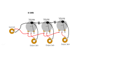
Hope someone can help me id this power transformer and specifically how to wire it for 120V. It has 6 leads on the 2 primary cores, and my very limited knowledge tells me that this is to simplify wiring it for 240V power source.
But I need it wired for 120V for my DAC
Also, when testing with a multimeter I get about 3.7 ohms between red and white leads, but nothing between black and red or white. Does it mean something is wrong with it?

Thanks!
CT-5082 label.jpg

noiseless small cooling fan source

There is plethora of choices on Bay but does any of you have a positive experience with any particular fan brand/design ? I need a small unit 3"x3" max to cool down overheating old cd player. I found in my junk drawer brushless 12V /0.18A unit and hooked it up to 5V power supply inside the player and can confirm it's effectiveness but it's way too noisy. It is a pretty old unit so maybe newer designs are quieter.

A Study of DMLs as a Full Range Speaker

Edit Nov 5, 2022: nice analysis and summary of DML materials and response with python script by @homeswinghome

https://www.diyaudio.com/community/...s-as-a-full-range-speaker.272576/post-7159983

Edit oct 27, 2021: a nice Google drive library of DML publications by vdljev:

DML - Google Drive

Edit April 1, 2020: nice summary of DML patents by Burntcoil

A Study of DML's as a Full Range Speaker

Edit Aug 12, 2019: Nice summary here by BurntCoil on how to maximize performance.


I had some cheap exciters that I got from PE a while back and tested them out a while ago with a full 20x30in FC panel here:

Foam Core Board Speaker Enclosures? - Page 225 - diyAudio

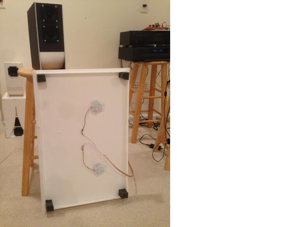
I found that a large 20in x 30in panel can sound quite good with nice bass extension and a snappy transient response:

403240d1393817181-foam-core-board-speaker-enclosures-fc-exciter-ob-1.png


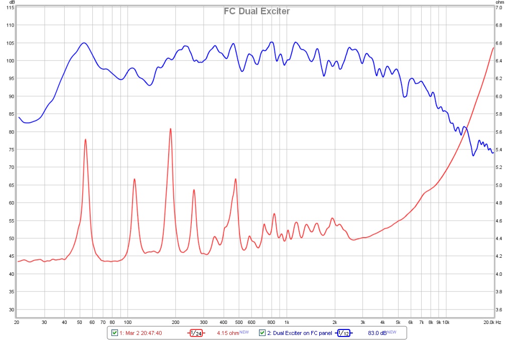
Impedance:

403242d1393817181-foam-core-board-speaker-enclosures-fc-dual-exciter-spl-impedance.jpg


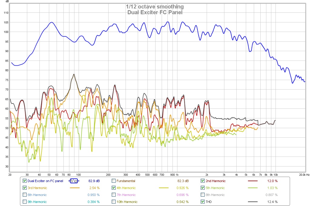
Frequency Response & Harmonic Distortion:

403243d1393817181-foam-core-board-speaker-enclosures-fc-dual-exciter-hd.jpg


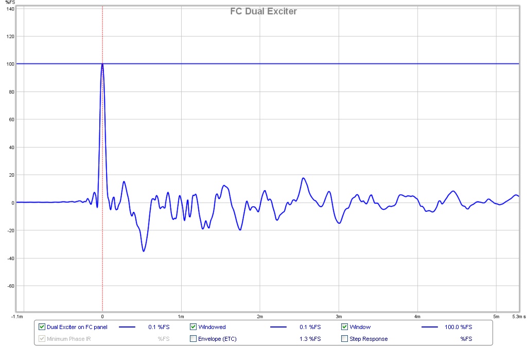
Impulse Response:

403244d1393817181-foam-core-board-speaker-enclosures-fc-dual-exciter-impulse.jpg


The results were interesting in that it sounded nice - with surprising bass and good midrange. I thought nothing more about it until recently prodded by the master of DML, CLS. He has worked on this extensively and is a treasure trove of good info. I since have discovered that you can really do some cool things with them by playing with driver placement, cutouts, adding mass, adding felt, adding ribs, making them huge, making them multi-way FAST, etc. the options seemed almost limitless. Take for example, a large center channel and a super 40Hz capable multiway that CLS built here: PIEZO NXT type panel - Page 60 - diyAudio and PIEZO NXT type panel - Page 61 - diyAudio

I feel like this technology just isn't getting enough attention. There are several very large threads on this on the web. It might be tough for a newbie to comb through. I am a newbie at this so thought I would document my journey for the Full Range forum to follow. I think it really could be a great full range speaker with some careful experiments. This will be really useful with some modeling using CAD and FEA modal analysis - such as available in many CAD packages like SolidWorks. One can play with shapes, cutouts, mass loading, variation in thickness and materials, boundary clamping conditions, etc. The idea is to spread the modes evenly with not any one mode dominating and causing a spike.

First thing is to play with it to get a feel of what we are dealing with. What is nice is that it is relatively cheap to play with. Exciters cost $3 to $20 ea and can be made by removing or cutting out large holes in the cone from an old driver and leaving the spider and VC to attach to the panel. Foam core or corrugated cardboard doped with shellac or PVA seems to be the materials of choice.

Some interesting facts:

1. Although it has no baffle, it is not an open baffle (OB) dipole in behavior - that is, there is no huge bass rolloff and it hits surprisingly low (40 to 50Hz is easy) for a zero baffle driver.

2. It is not a dipole but behaves more like a bipole or an omni.

3. It has very quick snappy transient response - nice drum sounds.

4. It is sensitive to how you mount it or frame it or hold it.

5. You are building a driver in reality - a driver and zero enclosure.

6. You want to avoid symmetric shapes and symmetric exciter placement in order to reduce the effects of the main symmetric transverse drum head eignmodes. Think reflection anti-symmetric shapes like uneven trapezoids, pentagons, blobs, etc.

7. It operates more by having high velocities and large areas for good efficiency vs large displacements - thus small drivers and large panels can be surprisingly loud.

8. The impedance is essentially "flat" relative to normal drivers in that there are modal peaks (many of them) but they range from nominal Re value (say 6 ohms to maybe 8 or 9 ohms throughout the 40Hz to 20kHz range - this presents a very flat load to an amplifier.

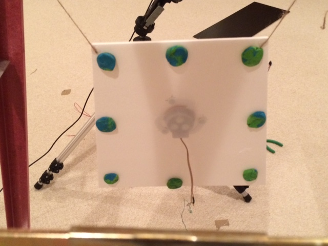
Here is a photo of a basic panel I was testing (right before I cut off some edges to form a trapezoid) - panels is about 1 square ft in size and made of standard dollar store foam core board. I suspended it with two pieces of twine from the top corners between a ladder to reduce the effects of edge boundary clamping:

476004d1428319574-study-dmls-full-range-speaker-trapezoid-dml-80mass.png


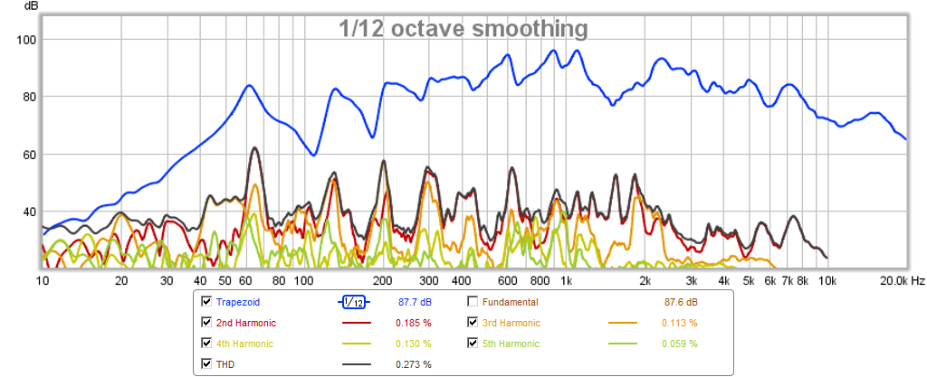
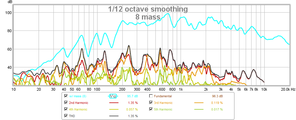
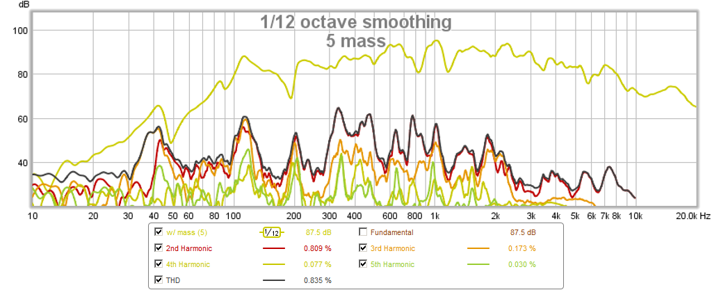
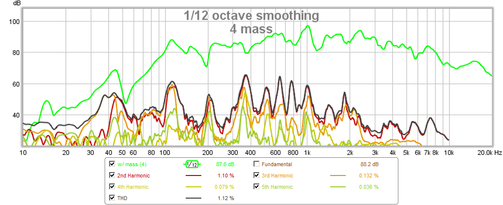
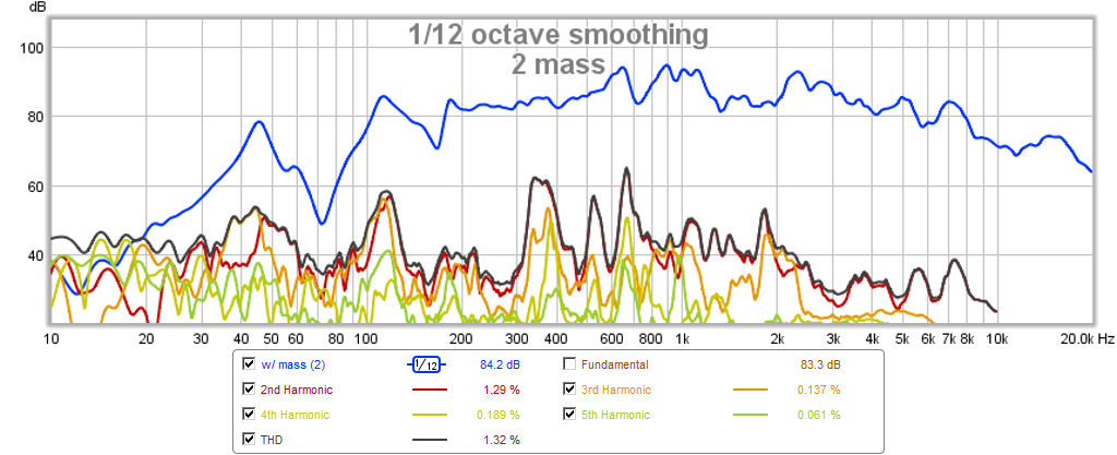
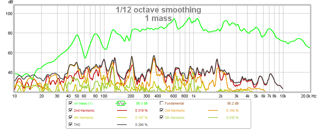
Then I started to play with mass loading by adding blobs of modeling clay (8, 5, 4, 2, 1, 0) so you can see the effect on the resonance modes and the harmonic distortion. What is neat with this test is you can do it live while playing music and immediately hear what sounds more pleasing to the ear. Note the 50Hz bass extension. It is also surprisingly efficient with 85dB and a puny little voice coil. These are 0.5m and 0.71v for equivalent SPL at 2.83v and 1m.

Frequency Response and Harmonic Distortion for...

No added mass:

476005d1428319574-study-dmls-full-range-speaker-trapezoid-no-mass.png


8 pieces of added mass:

476006d1428319574-study-dmls-full-range-speaker-trapezoid-8-mass.png


5 pieces of added mass:

476007d1428319574-study-dmls-full-range-speaker-trapezoid-5-mass.png


4 pieces of added mass:

476008d1428319574-study-dmls-full-range-speaker-trapezoid-4-mass.png


2 pieces of added mass:

476009d1428319574-study-dmls-full-range-speaker-trapezoid-2-mass.png


1 piece of added mass:

476010d1428319574-study-dmls-full-range-speaker-trapezoid-1-mass.png


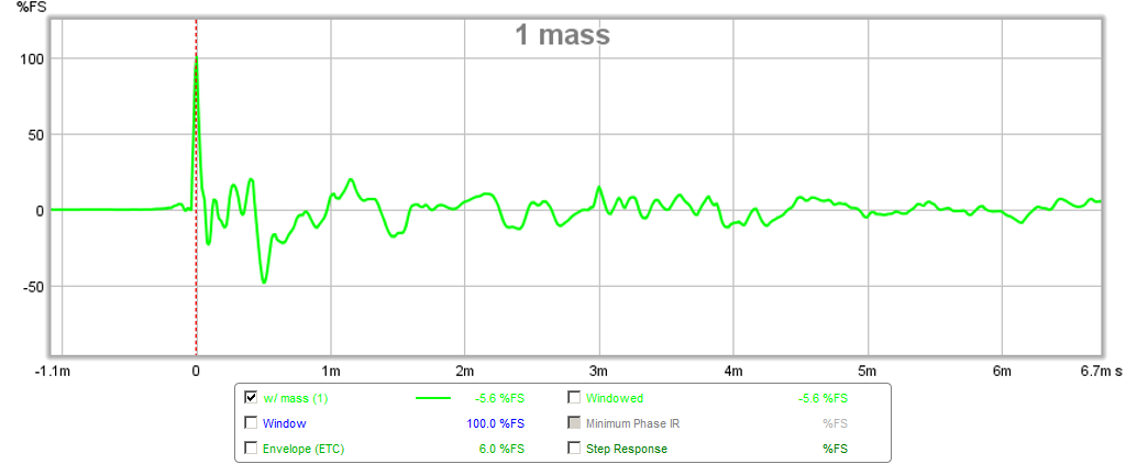
Impulse Response of 1 piece of added mass, note the sharp transient capability with relatively low after pulse or ringing:

476011d1428319574-study-dmls-full-range-speaker-trapezoid-1-mass-ir.png


I liked the sound of the 5 and 1 mass the best and for a FAST with a 200Hz XO, the 5 mass might actually do fairly well. Of course, sound clips to follow once I have more time to work on this. Just to demonstrate how quick and easy this is, I did all these experiments in less than an hour including making the DML.

Attachments

  • Trapezoid-DML-80mass.png
    Trapezoid-DML-80mass.png
    396.1 KB · Views: 42,722
  • trapezoid-no-mass.png
    trapezoid-no-mass.png
    146.4 KB · Views: 39,775
  • trapezoid-8-mass.png
    trapezoid-8-mass.png
    146.4 KB · Views: 38,989
  • trapezoid-5-mass.png
    trapezoid-5-mass.png
    151.4 KB · Views: 38,948
  • trapezoid-4-mass.png
    trapezoid-4-mass.png
    151.7 KB · Views: 38,625
  • trapezoid-2-mass.png
    trapezoid-2-mass.png
    151.3 KB · Views: 38,396
  • trapezoid-1-mass.png
    trapezoid-1-mass.png
    143.7 KB · Views: 38,152
  • trapezoid-1-mass-ir.png
    trapezoid-1-mass-ir.png
    40.5 KB · Views: 37,648
  • Like
Reactions: 4 users

For Sale Amplifier Denon POA T10

p23q0y9i.png

Hello for everyone..
I am selling here my Denon POA amplifier in perfect working conditions and mint appear, selling here
because I do have more equipment of the same kind but can't stay with everything also for invest in
other stuff so looking for a new owner. payment by PP
Price is 440€
Regards

Attachments

  • tyiougua.png
    tyiougua.png
    272.8 KB · Views: 35
  • w0ukcn3k.png
    w0ukcn3k.png
    275.3 KB · Views: 38
  • 7pb8ydd5.png
    7pb8ydd5.png
    304.4 KB · Views: 39
  • vgogmb3u.png
    vgogmb3u.png
    271.9 KB · Views: 35

What is going on with HifiEngine?

I was just wondering if anyone knows what is going on with HifiEngine?
Since the past month I think, registrations are not possible anymore.
I've read some posts in this forum about HiFi-Engine being very paranoid.

My IP-Address was banned for no reason and I didn't even have a user account. I just tried to make one. (Maybe I tried it too often...)

Besides that, I was wondering if someone could help me with getting some documents from HiFi-Engine, as I cannot register nor can I download anything. I do however manage to view the site by using a VPN.
I just can't register and now registrations are closed.

Thanks in advance.

One BJT line amp/buffer

I need your kind help with one challenge I have. I call it a challenge as I am in disdain and not experienced with BJT-circuits design.

Topic: I would like to use one-BJT (not two or more) for providing a single audio Line Out from many sources Inputs of various output impedance (some are low, some are high) via a switch. Practically it should be a buffer with much larger input impedance than any of the inputs, I softly guess.
Now, comes the hard part of the request:
  • SNR: > 100dB
  • THD @ 0dB: < 80dB for even, and <90dB for odd ones
  • headroom: 14dB (amplitude 5V)

Of course, I could use the switch alone, but the sources are not properly buffered and I am afraid not to mess them up.
The input signal amplitudes are scaled to 1.0V (0dBuRMS)
I have a +18V PS, regulated.
The one-BJT can be NPN or PNP, whichever. I can care less about this.

The first attempt I made it ended lousy: I used a BC547 with CC topology. The output signal has 2-nd harmonic (-40dB) already present even at low amplitudes. At around 0.5V amplitude it started to show huge distortions, both even and odd. Examination show that the positive side are softly compressed, enough to get now ALL harmonics at around -40dB.

Attached the CC-topology I used. The simulations did not show these distortions.
The measured DC voltage on emitter is indeed 8.5V as simulated.

Any hints? What I did wrong?
Is it at all possible to fulfill the above requirements with only one BJT?
Which topology and schematic/components would be better (still one-BJT topic frame)?

P.S. I saw too late that my title is a bit off. This is not a mixer, rather a line buffer. Sorry.

Attachments

  • Screenshot_10.jpg
    Screenshot_10.jpg
    168.3 KB · Views: 579
  • Like
Reactions: 1 user

How to improve your AC power

I had tried using inverters and big batteries to make my system sound better.

I sincerely think they did work initially but even the GIANDEL rated for 5000 watts inverter could not handle supplying a constant 500 watts total for four THF51 based amplifiers for the two hours I would usually listen. At the end they began to act strangely and make funny sounds so I returned to AC and continued to use the FO-FELIX filters that have been very popular for years in the GROUP BUYS section.

It was obvious that AC from the wall was superior. I do not doubt the inverters had a soft fail. No one wants to buy a new inverter every year.

The inverters produced a 22 kHz spike one could see with RTA - though I could not hear such a thing one has to figure it could produce problems at lower frequencies. I could never figure out if the noise emanated from the inverter or the AC wires coming out from it.

In December I took a look at AUDIO ASYLUM, which I do not do very often, and saw a post from a fellow talking about ground boxes and using Rochelle salt to control AC noise. I know the first time I saw an ENTREQ box I laughed as most did. I could never bring myself to pay that kind of money for a box with stuff in it but being a DIYer I would not mind building something and hearing it for myself.

The post directed me to HEAD FI and posts by cdacosta : https://www.head-fi.org/threads/diy-ground-box-thread.968372/

This begins with a basic guide to the ideas presented in the thread.

I bought the Rochelle salt in December and am just getting around to using it. It seemed simple to implement and it is simple to implement.

I have treated a bit over half of the switch plates and whatever you call the ones that cover receptacles in my upstairs and can say what this does is extraordinary. It does allow a reduction in noise which is about the only way to explain the far greater level of detail one will hear. cdacosta assures that the more "junctions" are treated the better. He goes into detail about tuning the amount of salt used. I am pleased with using his recommended starting point. I could hear what this does with treating the cover over my system AC receptacle. After that I started installing them in more and more. The subsequent ones do not make anywhere near as large a jump as the first one but there is a cumulative effect. Acosta assures than when his whole regimen in followed one will be amazed at what one can hear. This the combination of the salt packets, ground boxes and wraps around power cables which are all easily made.

Still waiting for the materials needed for the ground box - the magnetite (the main component) has been delayed. Cannot wait to try this. Starting with two - I use three DACs in my tri-amplified system - the main speaker left and right DACs will get them first.

The boxes are easy to assemble - I am using the recipe in the article except for little things like using hide glue I had on hand instead of the stuff recommended.

I figure what this is doing is like good cables - what is revealed could never be revealed by any other method. Some may think it is nothing more than band-aids but I counter what else do we have and we should be grateful for band-aids that work.

I was thinking last night - most of the AC work (I think of Michael Fremer's impressive AC wiring into his listening room) revolves around conductivity - removing obstacles in the path and this is important especially if one uses monstrous amplifiers to drive insensitive speakers which strikes me as wrong but that is another subject - instead of concentrating on radiation. I share with Acosta a suspicion of shielding - of course, if you absolutely need it you have no other choice but to use it - but if you do not absolutely need it it is BAD. So like naturopathic medicine we want to absorb the radiation instead of blocking it - sorry for the awkward analogy but I think it makes sense. Mr. Acosta may very well disagree with all that I have written here. Not to discount a free flow of electrons in any way but the worst aspects of the sound we attribute to our great friend and colleague AC POWER is the radiation that infects everything in its wake.

In my clumsy way I hope I have encouraged the kookiest of you to look into this. As I wrote to my audio friend in Toronto last night, the great Grant Warecki with ears that continue to amaze me, Acosta's concept is valid and important.

Just try the salt packets in a few "junctions" and hear what happens.

Help with vintage tube amp parts replacements

I have this vintage Audio Tekne power amp from Japan. There’s distortion in the left channel. Swapping tubes does not change anything. The distortion remains on the left channel.

This is fine. I’ve been told it’s likely a bad resistor. Seeing as how I have to take it to a local tech, I thought it may be a good opportunity to improve what I can while I have it with a tech.
First plan is to replace those sandcast resistors with mills resistors(or any recommended resistors of high quality) of higher ohm rating to lower bias and not run these NOS GE 6550 tubes so hard at 90mA even though I’ve read the GE 6550s can handle the high bias.

The point of the question. Does the capacitor on the tube socket make a difference in sound quality? I’ve seen Kondo builds where the electrolytic looks bypassed with a small film cap. Does that mean putting a film capacitor would yield sound changes/improvements easily heard?

Attachments

  • IMG_2029.jpeg
    IMG_2029.jpeg
    92.2 KB · Views: 95
  • IMG_2006.jpeg
    IMG_2006.jpeg
    428.4 KB · Views: 96

System Pictures & Description

I invite everyone to post a picture and description of their systems. Comments are welcome!
(Mods: It may be useful to make this thread sticky or move its location)

My system was put together on a grad student's budget - i.e. next to nothing. I built the speakers using vintage Alnico drivers from Dave aka planet10. I built the stands very cheaply from plumbing parts. Currently, I'm using two Sansui amps; one for the speakers and a second for the stereo subs seen under the desk. I'm currently gathering parts for a Mini-Aleph that will replace the Sansui driving the main speakers.

The sources are a Panasonic CD player, a belt-driven JVC turntable, and 10 GB of MP3s from my computer. I also have a Rega Planar2, but it's currently being used in the HT system. The preamp uses a single +24V power supply to run the 12AE6 space-charge triodes and heaters as well as the TI BUF634 buffers.

Cheers,
Eric


Complete system:
An externally hosted image should be here but it was not working when we last tested it.


Component rack:
An externally hosted image should be here but it was not working when we last tested it.


Pete Millett Hybrid preamp/headphone amp:
An externally hosted image should be here but it was not working when we last tested it.


Component rack, stylized picture :
An externally hosted image should be here but it was not working when we last tested it.

6AR6 Push Pull Triode Stereo Amplifier

I've been accumulating tube amplifier parts for many years and decided now that I'm retired I'd spend a little time and put something together. I like the lower distortion and better load dynamic load handling of push pull triode outputs so I was designing for that. I had a pair of 6000 to 4/8/16 ohm transformers that had been removed form a 30W Sansui integrated amplifier. I don't recall the model number, I bought them many years ago from a person that was parting it out. I had a number of 6BG6 sweep tubes including several that were very well matched that I was planning to use as my outputs but I could only get about 10 watts RMS from them and that wasn't quite enough for the speakers I have. My goal was 15 to 20 watts even though I realize that's not much more than 10, it is enough to listen to the speakers in my work area without them clipping.

I experimented with a couple other tubes but then decided to try the 6AR6 triode strapped. I'd read about them many years ago but had never actually designed anything with them. They are pretty readily available and are an inexpensive alternative to most other power tubes. I looked at their tube data curves and looked like I'd need on the order of 450 volts on the plate and a -75V bias to get 20 watts RMS in class AB1 with my transformers. So working backwards I needed about 150 volts peak to peak from the drive stage. I'm fortunate to have collected many power transformers over the years and I had one that was rated at 380-0-380 at 350 mA. That allowed me to use solid state rectifiers for the driver and get a 550V DC supply to regualte down to 525 and also get 450 from a tube rectifier with a CLC filter. I've had good results with the 6SL7 long tailed pair with a constant current bias and using 525 volts and large value (220K or larger) plate resisotrs. I follow that with a 6SN7 cathode follower so the bias resistors don't load the 6SL7. The 6SL7 is capable of a very linear output over a large (nearly 300V) output. One gain stage wasn't quite enough so I fed the long tailed pair with a 6SF5 triode. I could have used many different parts there but since the other tubes were octals I went with the 6SF5. It's not used that frequently but it has a mu of 100 and is much less expensive than a 12AX7 or 12AT7 and it is an octal base tube.

The inductor in the CLC filter is a 5H 300 mA choke, way larger then what I needed, but again I had it and it does have the benefit of low series resistance. I've tried both the 5V4 and 5U4 rectifiers on this amplifier, the 5V4 gives a higher DC voltage by about 15 volts under full load. At some point I'll try a 5AR4, but I only have one of those so I wanted to make sure eveything works first.

I did some breadboarding first and then when I was reasoanbly happy with the results I put this together. The driver stag ahs a voltage gain of approximately 65dB and the entire amplifier has an open loop THD under 5%. Closed loop, I can get 20 watts RMS per channel with 0.05% THD at 1 KHz and 0.15% at 20 KHz. At 5 watts out the THD is well under .05%. I got tired of setting up meters to adjsut the bias so I used inexpensive digital voltmeters across 10 ohm cathode resistors to measure and set the bias. I can adjust the level and balance for the outputs. I'm currently running them at 32 mA, I started at 40 mA but there was no advantage to that higher current.

I included a top and bottom view. The fuse was not yet connected when I took the picture.

I enjoyed building this amplifier and welcome and questions and comments. If anyone is interested I'll post the schematic.

frontTop.jpg
bottomView.jpg


top1.jpg
  • Like
Reactions: 1 user

Help with HK/Silver pre/power combo

I've recently recapped my Silver SP5050/SA5050 combo, which is almost the same as the HK725/770. There's 2 things that I haven't been able to work out though that I'd appreciate help on.

I'm using a known good CD player as the audio source.

1. Every time I turn the amp(s) on and play music, there is crackly distortion for about a minute, both channels impacted. This is not caused by pots being turned, and it goes away I guess once something warms up. But if I play music for 20 minutes so everything is warm, turn it off and then turn back on straight away, the same distortion is there for a minute. I've replaced all the electrolytics plus a couple of transistors, but wondering what that behaviour could be a symptom of?

2. The left channel for the "A" speakers doesn't work. The LED power display comes on, showing a signal for both channels, and the "B" speakers work fine. As far as I can see, there is one relay for A and another relay for B, so on that basis I guess there is some sort of fault on the actual speaker terminals or the board they mount on. Is that correct?

Pearl 3 Burning Amp 2023

Here is a PDF of of the Pearl 3 from Burning amp 2023 for those of you whom already have circuit boards.


Pearl3_BA2023.jpg


EDIT: Video presentation on Pearl 3 for BAF '23 can be found here - https://burningampfestival.com/videos/


EDIT: Build documentation "Pearl 3 Phono Build Doc-1.0c" is attached below. Version 1.0c is the most current. Download and print.


EDIT: Interview with Wayne about Pearl 3 - #881

EDIT: Modushop/ HiFi200 Chassis set available here - https://www.diyaudio.com/community/threads/pearl-3-burning-amp-2023.404054/post-7538807 https://modushop.biz/site/index.php?route=product/product&product_id=971

EDIT: Online build guide - https://guides.diyaudio.com/Guide/Pearl+3/28

EDIT: SMD soldering tutorial using Pearl 3 - Login to view embedded media

Attachments

  • Pearl3_BA2023.pdf
    123.7 KB · Views: 2,059
  • Pearl 3 Phono Build Doc-1.0c.pdf
    1.3 MB · Views: 1,048
  • Like
  • Thank You
Reactions: 39 users

Looking for a vector network analyzer for audio circuits

Hello everybody!

I am looking for a vector network analyzer that can measure audio signals (20kHz down to 20Hz).
I know that the "best" solution would be just using the soundcard from the computer and some software but I want a standalone device.

I already searched online but I only either found audio analyzers that would just analyze a incoming signal (no built in signal generator) or I would find vector network analyzers that worked from 9kHz to a few GHz.
But I want an actual VNA for audio frequencies.

Can anybody recommend me anything?

Crossover questions

I own a set of Vandersteen 2Ce Signatures. I just purchased a Vandersteen Model 2W subwoofer on eBay. It has not yet arrived, but I’ve been doing some reading, and it appears that I will need a pair of in-line crossover between the preamp and the sub. Apparently Vandersteen supplied these with the product, but they are now scarce and expensive.

Apparently, the Vandersteen x-overs were variable according to the input impedance of the amplifier. This is confusing to me. Since the sub is self-powered, I would assume that any relationship between the sub's amplifier and the preamp should be handled without an external device. If the amplifier in question is the amp that is powering the main speakers, then I’m also confused – but I’m often wrong. (FWIW, the input impedance of my main amp (PSA BHK 250) is 50K single ended and 100K balanced.)

I happened to notice a set of line of in-line crossovers from Harrison Labs (https://www.hlabs.com/products/crossovers/). The only variable with them seems to be the crossover frequency - not the input impedance of any amp.

I wonder if these crossovers would meet my requirements. Any assistance would be greatly appreciated.

Problems with air speed in ducts (WinISD)

I'm designing a box for an 8" woofer, when I see the air speed graphs in the ducts it's always absurd values and when I fix the duct it's more than a meter in size
What frequency do you recommend for this box? I tried co, 30, 35 and 43.49 Hz
Here are my woofer settings
I tried to make it work in a sealed box so the spl disparity between the sealed and ducted box really discouraged me, as the midrange has a very high spl in comparison.
1717201493920.png

1717201522202.png

1717201594281.png

Attachments

  • Bomber.pdf
    423.9 KB · Views: 11

SET amp power transformer hotter with KEF speakers

Hello, I have got a Line Magnetic Mini 218ia, single ended triode, 3+3 watt. The room is not small by italian standards, 46 square meters, but t is a nearfield listening set up, I'm about 2.5 meters away from the speakers.

I have been driving with it a couple of Triangle Plaisir Lymna bookshelf speakers, rated at 90 db/1w/1m, nominal impedance 6 ohm, minimum impedance 4.1 ohm. These are Triangle data. The 90 db of sensitivity may be a bit overrated but it worked well. I used the 4 ohm tap and listened with the volume knob at 9 or 10 o clock.

Line Magnetic specify that the amp can drive 6 ohm speakers, they say to try both the 8 ohm and 4 ohm taps to get a better result.

I now got a couple of Kef Coda 7 from the late nineties. Rated by Kef at 91 db sensitivity. Nominal impedance 6 ohm. I found an old online review where they measured a minimum impedance of 4.6 ohm and a slightly lower sensitivity, 90 db 1w/1m. They didn't talk about phase angle.

These Kef are more efficient than the Triangle, I use the 4 ohm tap and listen with the volume knob at only 7 o clock.

I prefer these, they have got higher sensitivity and a more british, relaxed sound. But the amplifier power transformer gets hotter with these. It is not scorching hot to the point of getting burned, just hotter. On paper these shouldn't be a very difficult load for a tube amp, should they? I can't hear problems with the bass or signs of distortion. I have tried 4 and 8 ohm taps but they seem to work better with the 4 ohm.

Is the power transformer higher temperature worrying? Should I stop using the Kef?

Thanks in advance

Caladan by Clayton Shaw DIY

Inspired by New Record Day video about the Caladan by Clayton Shaw, I decided to do it DYI since shipping costs to Japan are ridiculous (and no international deliveries at the moment provided). My MiniDSP serves as an active crossover for two ICEPower 125ASX2 amplifiers. They sound amazing, using a Linkwitz-Riley filter 48db at 1kHz and some gain in the low end, Never thought open baffle speaker can have such a lot of low end, while the speaker membrane is barely moving. The speaker disapear and you feel like in a live concert. This works also for my music with distorted guitars, not only for the high end demo music. Bass guitars sound so real. This is the first day listening to them after waiting 3months for the delivery of the 12inch speaker drivers....I guess no burn in needed. Clayton Shaw chose the perfect drivers.....
DIY Caladan.jpeg
  • Like
Reactions: 5 users

Stuck with Sony TA-N88B

Long story. Got this vintage class-D amp with a borked power supply. After fixing the issue it went back to the agent who requested the repair. Fully functional. Its owner then requested a recap which the experienced agent duly executed. At powerup (on DBT) it went full latch-up. Sheepishly the agent (who shall remain nameless) came back to me after finding nothing amiss.

After two months breaking my teeth on it I found that the latchup is caused by the SITs not being switched off fully at powerup. Without the output transistors and the PWM in service mode (R119/69) it works like a charm. Now the latchup causes the power supply to be overloaded. Which is weird given that it would work fine with DBT previously. With the PSU overloaded the two gate supply rails (+/-120 V) don't rise enough to cut off the SITs. Which need more than 25 V to reach that point. I also found that the PWM modulator also goes in a latchup mode due to the current source Q103/53 not starting as its power rail also rises too slowly. I did manage to get it going by removing C155 (I am working on the right channel, left is still in service mode) and using an external power supply to get the gate supplies going. At first it would start reliably when switching on the external PSU but when I started to move SITs around that went south and now it is bursting or even flatlining fully latched up. I don't believe that the SITs are bad. The rush-in current limiters are both OK and when the amp does work properly get shorted with their respective relays. Apart from the plethora of PSU rails the circuit itself is not all that complicated but the chicken/egg situation has me utterly flummoxed. What is going on here and how can I fix it? It must be something silly that I am overlooking but for the love of all that's holy I can't see it.

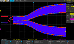
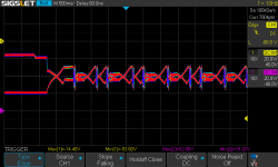
Scope images might illustrate. This is the gate drive of the SITs. This is a successful start with the external PSU:
SDS00805.png

And here it fails:
SDS00808.png

Once the PSU rails are established the rushin relays kick in, followed by the speaker protect relays. The slow rise is caused by the first stage of the PSU, which builds the primary regulated voltage (240 VDC). This is then fed to the second stage which provides mains isolation and all the secondary voltage rails. There are no less than eight. The PSU has not been touched, only the amp itself has been recapped.

Some new buys Garage sale stuff

I picked up a couple today. One pair is a home made set using cheap Jaycar drivers but the other set is some old Tandy
Optimus 5-B / # 40-2006
I hope they are the ones I want with the twin 16R tweeters doing the midrange and a singleton working up higher
Anybody here have any experience with them before I pull the drivers out and check the boxes. One thing tho; these are quite heavy and do appear to be both e=well constructed and in reasonable condition

Attachments

  • IMG_2999.JPG
    IMG_2999.JPG
    101.2 KB · Views: 21
  • IMG_3000.JPG
    IMG_3000.JPG
    85.5 KB · Views: 20

What's possible with a modern 3" Midrange ... 3way Prototype

I'm a fan of midrange domes since I heared big PMC monitors in a big room. Did a lot of designs with different drivers over the years and it seems like I settle for a design after all these years and trials.

I made a reference speaker for microphone measurements from 10Hz to 100kHz and a little striped down version of that you can see here:
Studio1 Proto.JPG

Unpacked my photography gear to get you a nicer few :cool: - but it's still not the final version as I plan it.
2x SB34NRXL75-8
1x M74A with custom frontplate
1x T25B
heavy and well made cabinet, closed volume for the 12"

Active amplification Hypex FA503 and a VERY quick DSP setup. Limiting is set to 10W for the 1" and 100W for the 3" - I need these drivers for the project :geek:
Measured in my listening/measurement room, close to the backwall. There are some room influences under 400Hz - the driver itself measures flat and goes down at about 40Hz, within the room level goes down 2dB but reaches deeper. Earthworks M50, Audio Precision ... measurement stuff is good. SPL level in 1m, measured with Sine Sweeps.

Frequency response at different levels:
Studio1 close wall - SPL.png


Here you see how positioning and room size influences and expands LF response. Closed speakers often go lower in the room and need less EQing as you think (5dB of boost for these measurements). Tweeter protection get's active at about 100dBSpl, the tweter itself should be good for maybe 105dBSpl. But these are SINEWAVES for measurements - it will be able to do significant higher peaks with music!
On the low frequency side you see that both 12" woofers go into limitations at low frequencies. This is impressive to lock at to be honest, there is a LOT of movement involved at these levels! And the woofer can take that missuse with no issue.
Only that single 3" is here to still play without any sign of power compression. Crossover was 500Hz and 2000Hz btw.
No resonances over 20kHz, piston behaviour up to 35kHz at least. The Hypex module is going down in level here - the tweeter would still be linear.

How is THD at these levels?
Studio1 close wall - THD.PNG


It more or less stays under 1% :oops:
About 0,2% is the lower measurement limit of the selfnoise from the measurement mic. You reach this limit at lower leves (not shown here).

You stay <0,1% from 60Hz to 5kHz at 90dBSpl - that's already LOUD in a room!
THD rises a little faster with the 3" from 500-800Hz but still is lower as most drivers available. Crossover at 500Hz is no problem at all, if you are not crazy with SPL level you can cross lower. And crossover 2kHz is also no problem for the 1" driver!

Of course there are many measurements missing here, not sure if I can find the time to do useful off axis measurements (cause I have to do them outdoors, needs setup time and a lot of measurements). But it should give a hint what a 3" dome midrange is able to do.
  • Like
  • Thank You
Reactions: 17 users

Klippel Near Field Scanner on a Shoestring

(Thread title inspired by @Boden from @bwaslo's thread "Xsim-3D development... I could use some math help")

A little background first: I've done many loudspeaker measurements with the tool set that many DIYers have, a calibrated mic and some free software, but I'm looking for a better system. I've been looking more closely at Earl Geddes measurement method, and Gabriel Weinreich's paper "Method for measuring acoustic radiation fields" and what I can find on the function of Klippel's Near Field Scanner. Bwaslo's recent thread "Xsim-3D development... I could use some math help" took a turn that made me want to start getting some help on understanding all this. And like Bill's thread, I could use some math help...

In addition, a number of very interesting questions were rasied to Earl Geddes about more advanced measurement methods that I think could use their own thread.

So so far, I have two big questions I'd like some help with, please:
1. what is needed to turn a measurement set into a view of radiation modes (for lack better way to ask the question)? Geddes uses a FORTRAN routine, but would something like open source mathematical software work, or is it best to have purpose built software?

2. Weinreich's paper and the Near Field Scanner both are capable of "sound field separation", in other words, they can pull the room reflections out of the measurement and give you just the direct sound from the speaker (no need for an anechoic chamber!). Klippel only appears to do this up to 1kHz (plus or minus an octave) and uses measurement windowing above that, Weinreich didn't appear to us it very high in frequency either. It appears to work by looking at the timing of sound waves passing through a pair of measurement shells? But what I'd really like to know is if Weinreich could do that with technology from the late 1970's, can intrepid DIYers do the same with available software and hardware today?

And please, if anyone else has questions about the function of more advanced speaker measurement systems, please post them here.

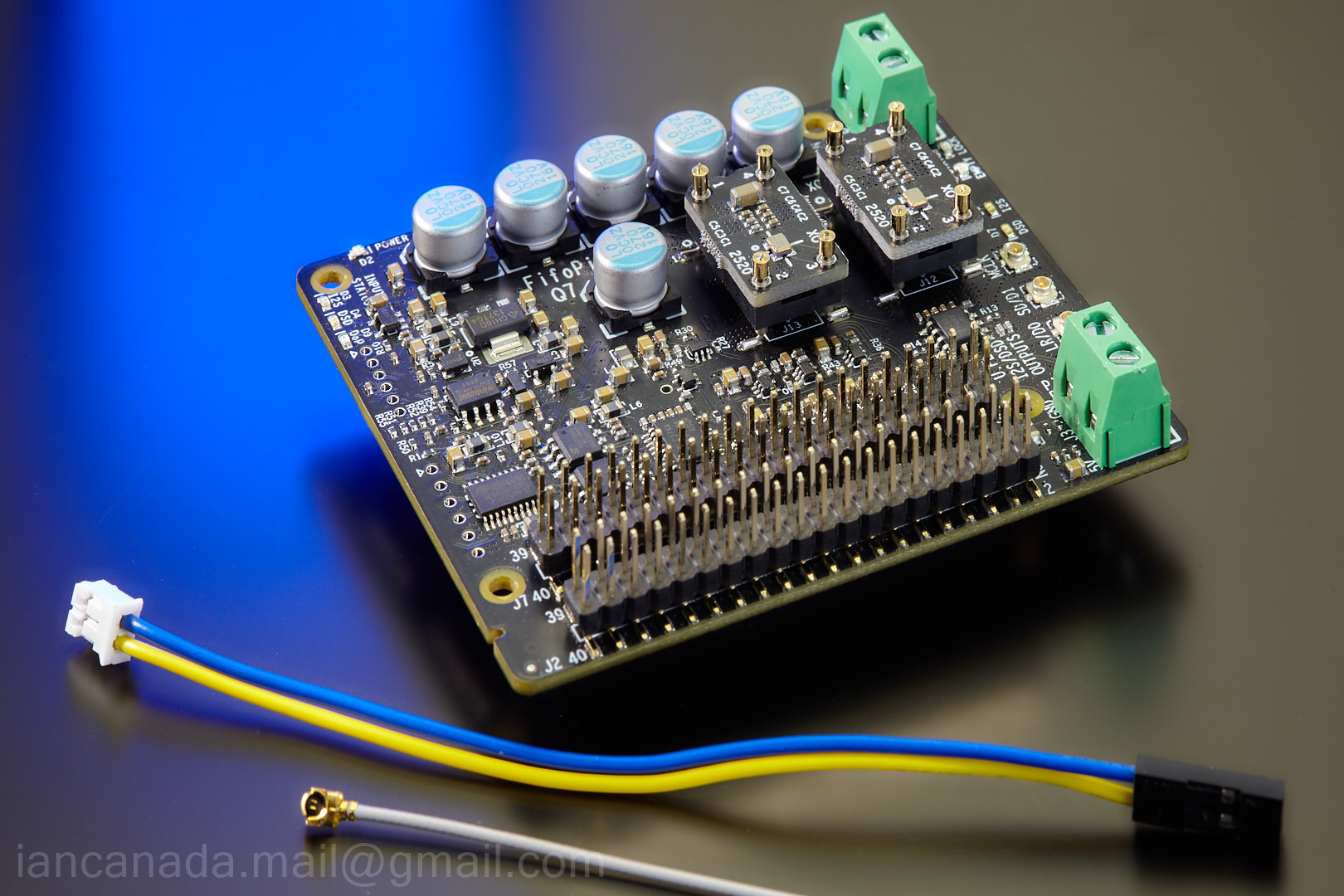
Asynchronous I2S FIFO project, an ultimate weapon to fight the jitter

People keep talking too much about jitter issues, but did less to make some kind of improvement. I decided trying to do something real – a working asynchronous I2S FIFO.

Before I go any further, I need to make something clear in advance:

1. FIFO is widely believed as one of the final methods to deal with jitter problems. But the asynchronous FIFO itself is just a technology which could provide a logic function to isolate the two clock domain. That means, for an I2S stream, digital audio data could pass through without any modification but the input clock was blocked and replaced with the new one. The new clock is totally independent from the old one except they should have the similar frequency. The FIFO logic itself does not influence the sound quality;

2. What really makes it sound better (or even worse) is the low jitter secondary clock. For example, if we have a new clock after the FIFO which comes with one digit ps jitter(RMS), we should get much better sound quality than before (the jitter level of the master clock from DIR chip usually around 50ps(RMS) level above corner frequency). So, we should pay more attention on the secondary clock and related interface. Everything connected to secondary clock has to be very carefully to deal with; otherwise new additive jitter will be introduced;

3. The size of the FIFO memory should big enough to meet overflow or empty time caused by the worst case of i2s input clock, but still has to be carefully selected to get the balance between the delay time caused by the working depth(usually half full) of the FIFO;

4. FIFO with low jitter secondary clock could only reduce the play back jitter for an audio DAC, but has nothing to do with the sampling jitter. I don’t have any idea if a CD was reordered with poor clock of the ADC.


The main logic functions could be achieved by a FPGA/CPLD chip together with a megabit SRAM. But the clock section has to use specialized clock/timing circuit, because the jitter performance of the output of FPGA/CPLD are far from what we want.

Below is the possible block diagram of this I2S FIFO project:
https://github.com/iancanada/DocumentDownload
https://twitter.com/iancanadaTT

FifoPi Q7 Jan.12,2023 update https://github.com/iancanada/DocumentDownload/blob/master/FifoPi/FifoPiQ7/FifoPiQ7Manual.pdf
FifoPiQ7_0 by Ian, on Flickr

Attachments

  • FIFOBLOCKDIAGRAM.jpg
    FIFOBLOCKDIAGRAM.jpg
    102.1 KB · Views: 34,141
  • FIFOBLOCKDIAGRAM.pdf
    11.6 KB · Views: 3,299
  • Like
Reactions: 1 user

Group Buy for Curve-Tracer-Matched 2SK3497 / 2SJ618 quads at 55°C

As mentioned earlier in the M2OPS thread, we were able to achieve much lower distortion with 2SK3497/2SJ618 than the popular IRFP pair :
https://www.diyaudio.com/community/...-and-maybe-a-power-whammy.390636/post-7173210

We also promised to offer matched quads of those, see here for details :
https://www.diyaudio.com/community/...-and-maybe-a-power-whammy.390636/post-7179541

We have now matched 300 pairs of those and can achieve a yield of ~80x NN-PP quads.
Spec is Vgs to 3mV between NN and PP, transconductance to 5%, and delta Vgs N-P within 0.25V.
This will have no consequence in the M2OPS-type complementary follower, as demonstrated by Twitchie :
https://www.diyaudio.com/community/...-and-maybe-a-power-whammy.390636/post-7206502

At 820HKD a quad, they only cost slightly more than 2x of a matched 2SK3497 pair.
This will include registered air mail and any PP fees.
As in the past 10 years, we only can ship FOB, and are not responsible for any postage losses.
Registered mail is not insured. But HK post has been proven very reliable in the past.
What happens at your end, they have no influence though.

You are free to order multiple quads, and will automatically be given Vgs close to each other.
We also have (only) 2 sets of Octets to the same spec, out of 600 devices.
Those interested in Octets should contact me by DIYA Conversation.

We only call for payment when GB is closed, and we are ready to ship.


Patrick

Accuphase P-7100 Amplifier Clone

Hi. I'm starting this new thread about my Accuphase P-7100 amplifier clone. Most of the owrk is already done, and I just completed both amplifier module last week.
I tested and preset both amp modules today and everything is looking good. I pre-set the bias at 5mV on the final instead of the specs 20mv (20mv / 2x 0.47R = 21ma / Transistors
The front end and Meter/Softstart/Protection PCB are tested and working fine. The main +/-75V Power supply is already assembled on the chassis. It is made of a massive recycled Rotel potted power transformer, two large 51,000uF/100V Kemet power capacitor, as the original just one 35MB100A, 35A, 1kV rectifier bridge and a copper GND bus bar as the original.

I'm trying to emulate as far as possible the original, since I know the Accuphase sound and love it. I went throught the service manual and decoded the detailled BOM that list all the type of resistors and caps used where (film, carbon, MOX, carbon film, and as far as possible the same caps series and type).

The PCB, original clone of very good quality (2mm, gold plated) are from ebay. All the pcb were replica of the original and match the service manual schematic, except the Meter/Softstart/Protection PCB. The original processor amp control was replace with discrete circuit, and the usual uPC1237 protection IC, but there was no info on it, and no part values. I had to find the circuit and test my mods by myself. The input stage pcb is the same circuit but the parts ID are different from the original schematic, and some small differences are there as well. I documented the changes and wire the board accordingly. Chassis is a clone from Aliexpress.

The original amp section used 2SC5358/2SA1986 (230/15A), me I'm using the 2SC5200/2SA1943 (same 230/15A) that I bought years ago, and match them myself.
I used thermal spread aluminum bars to mount the power amp transistors, and to add rigidity to the clone heatsink made of two section. The output amp module is now solid as a brick. The amp pcb also inclded nice brass bus bar and input transistor pairs rubber caps, as the original.

Here some pictures of the PCB. There are some extra PCB such as the rectifier PCB and Softstart and Ground Lift PCB.

Attachments

  • Various PCB.jpg
    Various PCB.jpg
    206.2 KB · Views: 184
  • Meter-Softstart-Protection PCB.jpg
    Meter-Softstart-Protection PCB.jpg
    216.9 KB · Views: 195
  • Final PCB (2).jpg
    Final PCB (2).jpg
    247.3 KB · Views: 199
  • IMG_20220204_132300.jpg
    IMG_20220204_132300.jpg
    299.9 KB · Views: 193
  • IMG_20220204_132307.jpg
    IMG_20220204_132307.jpg
    339.1 KB · Views: 153
  • Like
Reactions: 5 users

B+ dropped 15%

Hi, I don’t post much but I get great info from the group. I have a DIY Don Garber/Loftin White type 2A3 amp. My previous homes AC voltage was 123VAC and the PT is 750VAC center tapped. Per Don’s schematic I was within 1% voltage was at all the the critical test points. The PT is setup for 123VAC. My new homes AC is 119VAC. With changing anything or digging into why, my voltages have dropped like 15% and starts with the B+. Where should I start investigating for the reasons. Help is very much appreciated.

Folded Horn Acoustic Guitar Patent # 10,777,172

Hello all - I am new to this site, looks really great! I was granted a 20 year Utility Patent last year for my Folded Horn Acoustic Guitar. Patent # 10,777,172, can find on Google Patents of course. I have two five foot long folded horns inside an acoustic guitar. The horn is exponential and has a 1:8 ratio from throat to horn, with a speaker mounted to each compression chamber. This is long enough to capture the lowest frequency on an acoustic guitar at 1/4 wavelength. The true acoustic sound is a captured by a mic, not a pickup. Check it out and let me know what you think. CNC programming is complete, and will build a partial proto next week. Thanks!
  • Like
Reactions: 1 user

custom volume aby pedal

not sure what to call this other then a volume pedal even tho its not a pedal. i have some questions about how to wire it and not sure where to get the information so i figure id ask here.
basically i built this little box that looks like a amp and all it does it have a on/off switch for a power bar i mounted inside, and three volume pots with three outputs. the idea is i play through two amps and this will act like a ABY pedal. the third output is just for extra options (ideally for my rocksmith cable lol),

my problem is wiring it and grounding it, i seem to get a loud buzz from the output and i think its a grounding issue, i know using two amps can cause a ground loop aswell and ive had aby pedals that made this worse so i added some resistors between the grounds, i read on google about that but im not sure even sure about that.

here is the wiring i had

wiring diagram.png image_50438657.JPG image_67530241.JPG

this is what im building is anyone is interested
image_67213057.JPG

OB baffle design options

So...I have my drivers, I've tried a few prototypes, and I feel like it's time to get serious and I need to choose an overall geometry. I'm new to this and could use some help narrowing down baffle approach. I would say complexity and materials are irrelevant as I have access to CNC and design experts.

One main thing I don't fully understand is mounting the drivers. Rear mounting with chamfer or round over vs front flush mounting. I guess if someone wanted to give me some Coles notes on that I would appreciate it :)


I'm doing 18" (SB audience bianco18sw450), up to about 80hz, then 12" (jbl123a) up to... probably 500, then wide range (sonido 096 field coil)to 8000, then a tweeter/super tweeter, probably rear firing. Or I may let the wide ranger go all the way with no tweeter, not totally sure yet.

It is active and will be using minidsp for the two woofers so I can eq as needed.

Here are some primary options as I see it...

1. Wide baffle all the way, around 20" wide and around 45" high, with gradual round over on the edges, similar to the Sonus Faber Stradivarius U frame or partial uframe for the 18".

Reasoning: the wide baffle with large round over seems to give good defraction characteristics for the higher frequency. Pretty good looking if a little large.

2. Do the midrange completely baffle-less mounted somehow above a more traditional flat, wide baffle for the woofers.

Reasoning: no baffle at all for mid-high has best defraction characteristics...? The woofers will appreciate some baffle for cancellation purposes

3. No baffles anywhere. Nothing extends beyond the drivers.

Reasoning: again, defraction characteristics and off axis for mids and highs is good. Lows have zero baffle coloration. Also zero cancellation mitigation so needs a lot of eq.
Can look pretty cool.

4. Triangle. Baffle gets progressively larger as the drivers get larger. I could imagine benefits for off axis response similar to offsetting drivers due to the fact that the angles are changing for each driver, vs a parallel+perpendicular shape of a rectangle. Can look good.

5. Separate, different shapes baffles. Sort of looking at the pap construction but using the size most suitable (determined...with edge software?) for each driver. Similar to the triangle idea but with rectangles basically, and more flexible on size since each is separate. Large round over on all angles would perhaps guide much of the wave off the baffle before it hits the next baffle/driver?

Other factors, possibilities:
  • mount drivers in felt only, inlayed in a baffle
  • rear mount with drivers just barely touching baffle to reduce vibration

I may be wrong thinking in some, most, or all of this, because I'm new and dumb...

Hornresp

Hi Everyone,

Just letting you know that Hornresp Version 18.00 has now been released.

The Tapped Horn Wizard tool has been significantly enhanced. For a given overall horn length, flare rate and driver specification, the optimum driver position can be determined more easily than before.

Note that there are three ‘Interaction’ options. The operation of the first two should be pretty obvious from the titles. The third ‘L12 & L34 Linked’ setting enables the user to “slide” the driver along the mounting baffle / separating panel towards or away from the 180 degree bend (similar to changing the acoustic path length of a slide trombone).

Hopefully the Tapped Horn Wizard is now a far more useful tool. Enjoy :).

Kind regards,

David

Attachments

  • wizard.jpg
    wizard.jpg
    44.7 KB · Views: 23,648
  • Like
Reactions: 1 user

LT4320 based active rectifier

hello folks,
here is something i have been working on for some time.
I am willing to offer the pcbs as a group guy.
let me know if there is interest.
I will share a bom to GB subscribers, all mouser based, if GB goes ahead.
regards
Prasi

Edit 1: Group buy closed for THT PCBs, but still open for SMD PCBs. More info in the below link.
Group Buy List
group list qty_new - Google Sheets
Schematic SMD LT4320 rectifier LT4320 based active rectifier
Schematic THT LT4320 rectifier LT4320 based active rectifier
Schematic LT4320 CRC PSU PCB: LT4320 based active rectifier

Edit 2: Revision in prices. (price drop!)
LT4320 based active rectifier

Edit 3: GB closed for SMD PCBs. Only last 10 pairs of THT pcbs remain.

THT BOM BY MERLIN EL MAGOO LT4320 based active rectifier

EDIT 4: New GB for LT4320 based CRC PSU PCB Started..PCB's Produced and being shipped..-Completed and closed...
1. The Design: LT4320 based active rectifier
2. The PCB design: LT4320 based active rectifier
3. Physical PCB's: LT4320 based active rectifier
4. The BoM : LT4320 based active rectifier

EDIT 5: Group buy sign up has begun for modified SMD and THT rectifier boards with ENIG finish and earlier LT4320+CRC PSU PCBs. Please sign up at the below google sheet with your DIYA username and qty required against each pcb type.
LT4320 based active rectifier
Some 3D views of how the actual PCB assembly looks like
SMD: LT4320 based active rectifier
THT: LT4320 based active rectifier
CRC PSU PCB : LT4320 based active rectifier

Attachments

  • LT4320-NEW.png
    LT4320-NEW.png
    6.4 KB · Views: 7,015

Multiple identical transformers parallel connections

I would like to build a power supply with dc output of +-70V, 20A, that is switchable to +-35V, 40A.

I found 2 unit of 1000VA transformers with secondary output of 50V(10A) X 2.

Please correct me if I am wrong, there are some online information that suggested 2 identical transformers can be connected together to obtain double the current output.

Would the output be better connected before or after full bridge rectifier?

I found a few options of connection (see pictures). Please could some experts advise on the advantages/disadvantages of these connections?

Thank you!

Attachments

  • IMG_0530.png
    IMG_0530.png
    189.8 KB · Views: 22
  • IMG_0531.png
    IMG_0531.png
    192.1 KB · Views: 25
  • Like
Reactions: 1 user

Static measurement of DAC linearity possible?

I am considering the following measurement of DAC chip linearity and conversion accuracy (having 16-bit current output DAC in mind, like the TDA1541A):
Feed the DAC with an offset binary digital signal so that only the MSB has 1, all other bits are 0. The output current will be 2 mA. The accuracy of this current should be better than 1/2 LSB. The LSB current is 1/32768 * 2 mA = 61 nA. Half of this is about 30 nA. 30 nA related to 2 mA is 15 ppm. Is it possible to measure the output current with 15 ppm accuracy? The are precision 6.5 or 7.5 digit DMMs that could do it, I suppose.
What do you think about this idea?

Sealed 2,5-way All Dayton Build (1" and Dual 5")

Hello,

I posted a thread recently regarding a sealed 2-way all Dayton build (with 1" and 8" drivers) and I got a lot of help. Thanks a lot for that! As an alternative to that project, I started working on another sealed build with RST28F-4 and dual RS125P-8. It is for my 5.1 living room setup which has an 11" sealed sub. I would like to share with you some screenshots (crossover and full space response with diffraction) and it would be great to get your feedback knowing I am a beginner. My main questions are:

1- Is my design realist?
2- Do you see any flaws in the simulation?

Thanks in advance.


1 5 5 xover for diyaudio.jpg


1 5 5 diffraction for diyaudio.jpg

Aleph Jzm

IMG_5534-2.jpg


The first batch of kits has sold through. Those that have placed a pre-order for July - Everything is on track for on time shipping. This thread / post will be updated with additional details as they become available.

What Is An Aleph Jzm?

The Nelson Pass designed First Watt Aleph J is a classic. @Zen Mod created this version of the Aleph J to make the project more approachable to newer builders while maintaining the characteristics of the original. For more advanced DIYers and those that like to experiment, there are options to use a variety of JFETs and customize the circuit to suit personal tastes. For those that don't know Zen Mod, he was gracious enough to post a video to introduce himself and share a few thoughts. It can be found on YouTube.

What’s In The kit?

All the electronics components needed to complete a pair of amplifier PCBs, including 8 matched JFETs.

IMG_5118.jpg

What Is Needed To Complete The Full Project?

At this time, a complete kit including everything required to complete an amplifier is not available. You’ll need a power supply, chassis, wiring, and a few other parts. Everything you need can be purchased directly from the diyAudio store and well-known retailers world-wide. Suggestions are included in the build guide, and/or you can customize to your heart’s content.

What Skill Level Is Required?

This project is intended for intermediate to advanced DIYers. It may be the perfect project after an Amp Camp Amp. Newer builders willing to do a little studying should have no trouble following the build guide. However, it is critical that builders know how to identify parts from schematics, match those parts to PCB locations based on the silkscreen, and have good soldering skills. Most importantly, all builders are responsible for their own safety and must understand essential safety practices and precautions when dealing with mains powered electronics.

Feel free to review the Aleph Jzm Build Guide in advance if you're trying to determine if this project might be for you. The guide will continue to be updated. The Aleph Jzm Kit Build Support thread is also available if you have questions.

I’ve Heard There Is A Chassis For The AJzm

It’s not only for the AJzm; it just happens to work really well with the AJzm. More details can be found on Modushop's website.

More to come....
  • Like
  • Thank You
Reactions: 16 users

Need some info on DIY Paradise Eva 1

I have been given ann Eva 1 LDR remote control preamp, single RCA inputs and outputs. But it came without a wall wart power supply.
Anyone know what voltage and current rating the PS should be?
Also, which is the input and output pair?
Guessing inputs on the outer side, outputs towards the middle of the back of the enclosure.
Hopefully the balance is okay. LDRs tend to drift with time, it has been my experience.
Thx in advance for any assistance.
Cheers
Luigi

2x150W Amp module for sale

Hi, All

Announce some SMPS+Class D amplifier integrated modules here:

FFA001V3
Output: 2x150W @ 4 / 8ohm
Input: 85--265Vac, constant power SMPS
Size: 90x150mm
Price: $49.9/Unit, w/o shipping (Inc. I/O buffer and mating cables)

FFA001V3-HB

Note: Configured as a high-bass mode. CH1=300W@4OHM and CH2=120W@8OHM, similar to the Pascal U-PRO2
Price: $54.9/Unit, w/o shipping (Inc. I/O buffer and mating cables)

FFA002V2 (1U height)

Output: 2x300W @ 4 / 8ohm
Input: 85--265Vac, constant power SMPS
Size: 95x200mm
Price: $99.9/Unit, w/o shipping (Inc. I/O buffer and mating cables)

FFA003V1
Output: 1x150W @8Ohm / 1x300W @4ohm
Input: 85--265Vac, constant power SMPS, heavy-duty design
Size: 90x245mm
Price: $64.9/Unit (Inc. AL base plate and Volume IO buffer) w/o shipping


PM me if you need more information.
Thanks~

Pics of FFA001V3

FFA001_V3_2.JPG


FFA001_V3_5.JPG


FFA001V_V3_NEW_build.jpg


Pics of FFA002V2
FFA002V2_3.png


Pics of FFA003V1

FFA003V1.png


Misc
--- FFA001_V3 spec sheet & Test data;

--- FFA001_V3 & I/O_V1&I/O_V2 dxf file;

--- FFA001_V3 RearPanel_XLR 3D drawings;

--- FFA001_V3 RearPanel_RCA drawing and PDF;

Attachments

  • FFA001_V3_Data_Sheet-20220814.pdf
    995.4 KB · Views: 570
  • FFA001_V3 Testdata-0802.pdf
    87 KB · Views: 368
  • FFA001_V3_MechDrawings.rar
    360.7 KB · Views: 328
  • FFA003V1.png
    FFA003V1.png
    233.4 KB · Views: 259
  • FFA002V2_3.png
    FFA002V2_3.png
    1.3 MB · Views: 255
  • FFA001V3_RearPanel_XLR.pdf
    62.9 KB · Views: 130
  • FFA001V3_RearPanel_XLR.STEP
    107.4 KB · Views: 101
  • FFA001V3_RearPanle_XLR+IO.STEP
    7.3 MB · Views: 95
  • FFA001V1_IO_RCA rear BD.pdf
    13.3 KB · Views: 97
  • FFA001V3_IO_RCA rear BD.zip
    77.8 KB · Views: 91
  • Like
Reactions: 7 users
Projects by fanatics, for fanatics
Get answers and advice for everyone wanting to learn the art of audio.
Join the Community
501,768
Members
7,576,594
Messages

Filter

Forum Statistics

Threads
392,360
Messages
7,576,594
Members
501,768
Latest member
mikekasky