You are using an out of date browser. It may not display this or other websites correctly.
You should upgrade or use an alternative browser.
You should upgrade or use an alternative browser.
Full Range EQ
- Thread starter Nelson Pass
- Start date
I am contemplating potentiometers in the R3 and R5 positions for maximum tuneability. 🙂
The n00b question of the day is: I assume that a linear potentiometer in these positions would give the ”right feeling” of EQ response, as apposed to a logarithmic potentiometer.
Am i right or wrong about that assumption?
The n00b question of the day is: I assume that a linear potentiometer in these positions would give the ”right feeling” of EQ response, as apposed to a logarithmic potentiometer.
Am i right or wrong about that assumption?
Any pics in particular?
if you mount it in case properly grounded (screws) it'll not buzz
I have a couple of questions about the 100k potentiometer in this circuit. First, I'm assuming a dual/stereo audio/log taper, correct?
Second, When the pot knob is turned, what actually happens? I'm planning on using a 10-position, 4-pole switch to change R3 and R5 values to choose the curves per NP. So, I'll have two knobs, one of which will select a curve. The pot's the other. How would I use and label them?
Second, When the pot knob is turned, what actually happens? I'm planning on using a 10-position, 4-pole switch to change R3 and R5 values to choose the curves per NP. So, I'll have two knobs, one of which will select a curve. The pot's the other. How would I use and label them?
I'm hoping to get assistance here for my full range drivers, which are Tang Band W3-665SC(there are very large number of these out there, as Logitech used them for years in their THX multimedia systems).I also have EQ files for some specific full range drivers...
I have both the Manufacturer data sheet, and a text file of measurements in my listening room.
Any success with the F15's and supertweet? I've got a pair of F15's in some Caintuck style/sized temp baffles that might welcome this EQ.
Thanks Woody, I had come to that conclusion based on a closer reading of the circuit and description
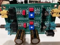
Hello,Very grateful for your help, I’m getting 11 volts at the first capacitor and zero at the second.
I was once again looking up at this circuit closely, and I noticed something wrong in the schematics?
The voltage dividing resistors, shouldn't they both be 4.75 k, so we get half the supply voltage at this point (where the + of the 1000 uF cap is attached)
There should be only one 47.5 ohm resistor, not two (the one that comes from + supply).
Also, in the article I read that "A bass equalization circuit is formed by C1-C2 and R1-R3".
Shouldn't it read R2-R3? R1 is just to bias the jfets, isnt'it?
I still think the circuit is wonderfully simple for what is does, but some folks may be confused, so I just wated to make sure that it is right.
Kind regards,
Vix
Awesome read! 
I did something similar in 2021 for my Alpair 12Ps in onken-ish cabs and it did make them much flat. It was a passive one, placed between the pre's output and amp's input, so it lacked the gain at LF but with the curve looking somewhat similar to yours. It was a very revealing experience.
I did something similar in 2021 for my Alpair 12Ps in onken-ish cabs and it did make them much flat. It was a passive one, placed between the pre's output and amp's input, so it lacked the gain at LF but with the curve looking somewhat similar to yours. It was a very revealing experience.
Those pair of 47 ohm resistors and the 4.75K resistor are not acting as a voltage devider.
The first 47 ohm resistor and 1000 uf cap is just a power suply filter and if we had 24V in
we might get ~ 23.99V out to the next 47 ohm resistor and 1000 uf cap but now might have
~ 23.98 V And that 4.75k resistor and led just tell us uou have the circuite powered on.
The first 47 ohm resistor and 1000 uf cap is just a power suply filter and if we had 24V in
we might get ~ 23.99V out to the next 47 ohm resistor and 1000 uf cap but now might have
~ 23.98 V And that 4.75k resistor and led just tell us uou have the circuite powered on.
Got hold of Fane 12-250TC full rangers as wanted to try a simple open baffle and here they are in progress. Got some inspiration from another post to have the wings as support for the baffle. Pair of some project wood 16”/3ft with wings being 5”/3ft 😊
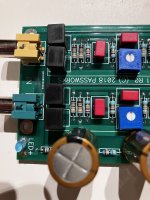
Now I wanted to use this equaliser kit that’s lying with me and anyone has some suggestions on what values needs to be changed for this driver?
So far initial impressions paired with LU amp and FE2022 is pretty good but wanted to try this equaliser to tame the highs and improve the lows as what’s intended by Papa in his article
Thanks

Thiel small parameters of this driver

Now I wanted to use this equaliser kit that’s lying with me and anyone has some suggestions on what values needs to be changed for this driver?
So far initial impressions paired with LU amp and FE2022 is pretty good but wanted to try this equaliser to tame the highs and improve the lows as what’s intended by Papa in his article
Thanks
Thiel small parameters of this driver
Last edited: