Yes, me too, especially in combination with the sensitivity figures. You can get some piston action of the plate for sub response with a stiff plate and loose suspension, but for the response to become balanced the mids and highs then need to be low. The exciter simply cannot displace enough to keep up at 50Hz otherwise.Given the trove of data in this thread, I'm very sceptical.
FWIW, I did stumble upon a research paper studying the effect of a soft RTV gel pad between the driver and panel for a DML woofer The claim is a significant increase in the maximum panel displacement (2 to 3 times) at low frequencies over that of a traditional exciter rigid mounting.
Something else to try ...a decent DML woofer is the holy grail for me ... May be as difficult to find as the original ! 😵💫
Eucy

Indeed. Some designs seem to to use uncontrolled 3rd mode resonance (with the concomitant weight and compliance) to "lever" a small driver movement into a large panel movement. But if the edges are not terminated correctly, it leads to unrestricted edge movement and this increases distortion.The exciter simply cannot displace enough to keep up at 50Hz otherwise.
The 1st, 2nd and 3rd modes need some semblance of carefully-controlled edge termination while still allowing sufficient excursion to allow good response.
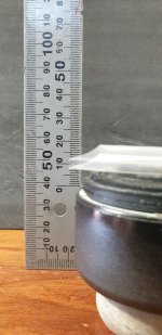
For interest, I recently measured the throw of a Dayton DAEX25FHE-4 exciter at 1.1mm in and 1.4mm out.Some designs seem to to use uncontrolled 3rd mode resonance (with the concomitant weight and compliance) to "lever" a small driver movement into a large panel movement.
A Dayton 3.5" TEBM65C20F BMR driver measured 2.5mm in, 2.9mm out.
So if it could be controlled, and the panel be able to bend sufficiently, the BMR driver should provide more base than the standard exciter...Yet to be tried
Last edited:
I've been wondering about gluing a neodymium magnet to a panel with a coil mounted on a brace on the frame so that there is no suspension. I don't think there's any way to get the flux density nearly as high without the steel, but can it be high enough?
Would it perform better or worse without springy suspension returning the panel to the neutral position?
I've found that distortion measures much lower when the exciter is not braced, which seems counterintuitive to me. But if un-bracing the exciter improves distortion, would un-suspension-ing it improve it more?
That seems to corroborate perfectly what I found on the 25HFE.For interest, I recently measured the throw of a Dayton DAEX25FHE-4 exciter at 1.1mm in and 1.4mm out.
A Dayton 3.5" TEBM65C20F BMR driver measured 2.5mm in, 2.9mm out.
So if it could be controlled, and the panel be able to bend sufficiently, the BMR driver should provide more base than the standard exciter...Yet to be tried
Attachments
That is worth checking out!I've found that distortion measures much lower when the exciter is not braced,
To me it seems like it should be the other way around. If making it more rigid with bracing increases distortion, why would making it more rigid by removing suspension reduce distortion?I've been wondering about gluing a neodymium magnet to a panel with a coil mounted on a brace on the frame so that there is no suspension. I don't think there's any way to get the flux density nearly as high without the steel, but can it be high enough?
Would it perform better or worse without springy suspension returning the panel to the neutral position?
I've found that distortion measures much lower when the exciter is not braced, which seems counterintuitive to me. But if un-bracing the exciter improves distortion, would un-suspension-ing it improve it more?
I don't have issues with distortion with my current bracing, but it is compliant and more of a suspension of the exciter.
I think in my most recent brace tests the distortion must have come from the entire (solid and heavy) brace vibrating. It makes sense to me now why any bracing has to be compliant. Holding an exciter against a 2x4 or any solid wood furniture does make quite a bit of sound, so making a big and heavy brace is not going to solve that problem like I thought it would.
Regarding suspension, I noticed some product material talking about Xcite XT32-4 having suspension that is tuned differently for better FR. If that really is effective, can it be made even better? I saw a comment from BurntCoil (sp?) that the best suspension is no suspension. Idk if that's true, but it seems like it probably is.
Regarding suspension, I noticed some product material talking about Xcite XT32-4 having suspension that is tuned differently for better FR. If that really is effective, can it be made even better? I saw a comment from BurntCoil (sp?) that the best suspension is no suspension. Idk if that's true, but it seems like it probably is.
It does make sense. The point of suspension in a driver is to suspend the cone. With magnet attached to the plate, and coil to a stiff bracing, the plate itself would suspend the magnet.
Your typical Dayton and Xcite are intended to be used without bracing, or at least to be easy to integrate in most designs. If doing a complete design with frame, plate and driver, I don't see why it would not work to fix the magnet directly.
At least in theory, but I do think it is quite hard and perhaps next to impossible to make such a design though. You need extreme precision to align magnet and voice coil. With the plate holding the magnet and being suspended in the frame, you need to be able to mount it very precisely and make sure it cannot move at all, even if the mounting should be compliant. Say you use a boundary around the plate like the spider in a driver/exciter. Even if you have same material and precision, it is now many times bigger, but the gap in the voice coil have not changed, so you will have less precise alignment and hence need a larger gap, so will get less sensitivity.
I think you're referring to the plate as the vibrating membrane itself. In such a case, you don't mount the magnet to the (membrane) plate. You mount it to a back-brace which is attached to the frame. The reason one would support the magnet is such a way is to prevent it sagging and eventually causing the voice coil to rub against the magnet in the pole gap.I don't get why you would want to mount the heavy magnet to the plate
The only thing mounted to the membrane is the voice coil. Nothing else.
Hello Andre, I think I mix up things because it is mentioned to mount the coil on the a brace/frame? So the magnet is on the suspended vibrating panel?I've been wondering about gluing a neodymium magnet to a panel with a coil mounted on a brace on the frame so that there is no suspension. I don't think there's any way to get the flux density nearly as high without the steel, but can it be high enough?
BTW Listening to my panels I liked the unbraced exciter better (I know, not scientific, just comparing side by side), but I decided to just go for a workable and reliable solution and stop trying to get the "best"results.
In the attached clips, the brown wooden bits are the braces. The stucco white is the vibrating panel.Hello Andre, I think I mix up things because it is mentioned to mount the coil on the a brace/frame?
Attachments
It is more or less the kind of braces I use. The right concept is in my plywood panel in a 3 part variant to avoid misalignment at the exciter.In the attached clips, the brown wooden bits are the braces. The stucco white is the vibrating panel.
Andre,In the attached clips, the brown wooden bits are the braces. The stucco white is the vibrating panel.
Cool drawings. But I think what HvdZ was referring to was Sapphire Sloth's idea (below) for a suspension-less exciter, rather than a mounting a conventional exciter.
I've been wondering about gluing a neodymium magnet to a panel with a coil mounted on a brace on the frame so that there is no suspension. I don't think there's any way to get the flux density nearly as high without the steel, but can it be high enough?
I think HvdZ might be right, in that the better option might be to mount the (lighter) coil and former to the panel, rather than the (heavier) magnet. But I also suspect Leob is also correct that getting good enough alignment of the magnet and the coil would be difficult in practice. It's an interesting idea, however.I don't get why you would want to mount the heavy magnet to the plate. The efficiency will be very low? If you want to get rid of the spider, why not mount the coil and former to the plate?
Eric
Sapphire Sloth,I spent many hours testing some things today and I started with some mounting tests. Here's this test frame:

Your frame reminds me a very similar frame I built in 2020 when I first started playing with DMLs. I wish I had pictures to share, it was exactly the same concept as your frame. Sadly, I got rid of it not too long ago as my collection of frames was starting to really pile up. Your frame looks a bit nicer, I must admit. I didn't bother to route out either of the two frame halves, I just used really long screws to join the halves. I put spacers between the two frame halves as I tightened the screws, to ensure that the pressure was pretty even around the perimeter. I could use different thickness spacers to control (crudely) the pressure.
Here is a link to a post I made at that time with a description of the frame and some results. Those results showed the best low frequency extension with suspension around the whole perimeter, at least for that particular panel.
https://www.diyaudio.com/community/...s-as-a-full-range-speaker.272576/post-6098619
I didn't actually recall this particular dataset until finding it just now, but I still tend to prefer the full perimeter suspension arrangement.
Eric
Hello Eric,Here is a link to a post I made at that time with a description of the frame and some results. Those results showed the best low frequency extension with suspension around the whole perimeter, at least for that particular panel.
https://www.diyaudio.com/community/...s-as-a-full-range-speaker.272576/post-6098619
I didn't actually recall this particular dataset until finding it just now, but I still tend to prefer the full perimeter suspension arrangement.
Nice to have the opportunity to remind this post. Are the REW mdat files still existing? It would be interesting to have a look to the spectrogram.
Christian
That pipe insulation idea is very interesting. Damps gently, blocks edge, and adds a little rigidity. I have only done a couple tests with 4ft tall panels of 2" thick XPS and 0.75" thick light EPS, and those test results were not good. I discarded the idea. Such a large panel seems too hard to control, using multiple smaller panels is a better solution I think, though I haven't actually tried stacking multiples.
I was stuck with using out-of-the-box dimensions of foam back then but now I have a hot wire table, maybe I'll try a big slice of a 2'x4' XPS panel soon. I do need to cut my last quarter sheet soon to make more test panels so maybe I'll test the whole thing before cutting it down.
I think the full surround makes sense for wider panels but I've been using this narrow tall aspect dimension right now and generally having surround on top and bottom only gives best results.
I ordered some butyl rope the other day and I'm going to try lining the edge of a panel with it or using it instead of foam in the frame. One problem with the pipe insulation might be noise that the panel makes when rubbing on the foam, if it rubs anyway. When doing preliminary testing of panels on my carpet floor I've noticed that the carpet on the panel edge does add measurable distortion. Adding my hand as a weight on top of panel helps lower that but it is still present. I think using CLD technique around the panel mounting points might bring significant improvement. Butyl rope should help to easily and cheaply test that idea.
Regarding mounting coil on panel, maybe that does make more sense, yeah. That would allow a steel pole piece to be used while keeping its weight off of the panel. It still has the problem of the magnet turning whatever it is mounted to into vibrating membrane though. Any compliant mount that way would surely cause distortion a different way by the magnet moving around in that compliant suspension and changing its distance to the coil.
It's been said several times that very precise alignment is needed for this approach, but that's only true if the coil gap is very tight. I'm wondering if there might be a way to change the design so that the coil gap can be much larger and less sensitive to misalignment. This will of course reduce sensitivity, but maybe that can be offset some with the design, and by using a bigger magnet. Maybe large subwoofer-style ceramic magnets on the frame and coil on the panel? They might produce too much sound from the magnet side though, idk. Or maybe just a large neodymium. Or maybe a parabolic arrangement of magnets.
Magnetic planar speakers already use this coil-on-the-panel idea. They are known for very low distortion so maybe the this sound-from-the-magnet theory is wrong.
I've also wondered about the size of the point on panel receiving excitation. I 3d printed some different mounting plates in the past to try different sizes for the point of contact, and some through-hole mounts as well. I didn't have any frame at the time though and I only tried it on some not-so-good panels so those tests don't really mean anything anymore. Best result on foam board back then was using a larger point of contact, through-hole, with a large washer-nut on the front side. 3" was the diameter I believe. Building a custom coil brings the question of how to best shape its point of contact with the panel, as well as questions about the ideal specs. I don't know anything about voice coil design, really
I was playing with FEMM and using an arrangement like this one below (three bar magnets) the field strength can be made more uniform in the Y direction without using a pole piece. These magnets are 1 units wide and 0.5 units thick. The difference in flux between the first green block and the second green block is just 9%. Those green blocks have a 0.25 unit gap between them which is larger than necessary if 1 unit = 2cm. With more tuning this could be normalized even better, and it scales fine.

The biggest concern is that there may not be enough flux in the gap this way. I attempted a comparison to a tight coil gap with and without pole piece using the same size magnet:

Not sure if this sim is correct but the left = 3.9e-7 T, middle = 6.04e-6 T, and right=3.24e-6. So the left is an order of magnitude weaker than middle. This doesn't account for the third dimension though and using long bar magnets would improve this a bit, as would increasing magnet size. It isn't too practical to increase magnet size in middle and right designs but in left design there may be a lot of room for bigger magnets.
The biggest concern is that there may not be enough flux in the gap this way. I attempted a comparison to a tight coil gap with and without pole piece using the same size magnet:
Not sure if this sim is correct but the left = 3.9e-7 T, middle = 6.04e-6 T, and right=3.24e-6. So the left is an order of magnitude weaker than middle. This doesn't account for the third dimension though and using long bar magnets would improve this a bit, as would increasing magnet size. It isn't too practical to increase magnet size in middle and right designs but in left design there may be a lot of room for bigger magnets.
- Home
- Loudspeakers
- Full Range
- A Study of DMLs as a Full Range Speaker