PMA said:mikek,
I just do not know what you are trying to do. Would you like to build a perfect hi-end amplifier (with perfect sound as well) or to solve an "interesting" circuit problem, regardless the sonic result? Unfortunately I did not see many people trying to solve both.
Pavel
simply exploring...
") ....
.......as for..'Would you like to build a perfect hi-end amplifier (with perfect sound as well)' .....i already have.....
Re: hi janneman
(A) No I haven't....
(B) They don't HAVE to be different, only if you want the two outputs not only opposite but also equal. There is no technical reason why two output voltages have to be equal and opposite, as the load is fully floated. So, even with each halves at the same gain setting (=different gain if one input grounded), it will work perfectly. On the other hand, in a power amp you may want it to be equal and opposite to maximise power output. But I must admit I hadn't realised this, so I learned something today.
(C)....220 and 110 would also have done it....
Jan Didden
mikek said:
(A) It would appear you haven't read the thread from the beginning
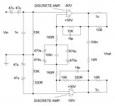
(B) ...if the amp. accepts only single-ended inputs, then the gains in the two halves have to be different...see text and fig. below:
(C) as for 330=165+165, i didn't have enough 330R in my bin...
(A) No I haven't....
(B) They don't HAVE to be different, only if you want the two outputs not only opposite but also equal. There is no technical reason why two output voltages have to be equal and opposite, as the load is fully floated. So, even with each halves at the same gain setting (=different gain if one input grounded), it will work perfectly. On the other hand, in a power amp you may want it to be equal and opposite to maximise power output. But I must admit I hadn't realised this, so I learned something today.
(C)....220 and 110 would also have done it....
Jan Didden
... ...may have to put some capacitance across feedback resistors ....
by the DJK....this......
http://www.mif.pg.gda.pl/homepages/...es/simp200W.gif
appears unstable..........
...may have to put some capacitance across feedback resistors ....by the DJK....this......
http://www.mif.pg.gda.pl/homepages/...es/simp200W.gif
appears unstable..........
ok folks...
so...its not apparently, merely a matter of cobbling two power amps. together to abtain a bridged output...hell no....
no...seriously, although each individual amp. may be unconditionally stable when used in single-ended output mode, this is not the case here....as we are infact using two units to generate twice the output.....
........in otherwords we have gain.....over and above that for which each amp. is compensated.......
note that the differential frequency response differs significantly from that of each individual unit....
...hardly surprising i suppose, considering, that one is phase inverting while the other isnt.....
...anyway, the important thing is that we'll have slightly different stability margins for each half.....and this has to be allowed for when modifying the compensation networks.
....so....the compensation in each unit has been made more conservative.......and some phase advance, (the 15p caps.), incorporated into the feedback network to gaurantee stability....
further reading.....:
http://www.national.com/an/AN/AN-253.pdf
...i am not entirely sure aboutmy zobel network values......may need to be looked at more rigorously...........
Attachments
djk said:While this method of bridging looks the best on paper, it usually results in a power oscillator.
Is the ± 50V power supply common for both halves? Dual mono supplies is no-no for a bridge amplifier, the ground currents are enormous. Strap the supplies together.
Try re-arranging the output zobels and the feedbck loop like this:
http://www.mif.pg.gda.pl/homepages/tom/files/simp200W.gif
The feedback loop cannot be DC coupled as yours is, plus the high end on the right half must be rolled off. The only ground is for the input off-set current .
When you are ready to give up and just want it to work, change it to this:
http://sound.westhost.com/project20.htm
...i think you've been proved wrong....

mikek,
it is interesting that one half needs pole FB compensation and the 2nd half needs pole/zero FB compensation, probably really resulting from poor behaviour of differential amps at higher frequencies ..
Pavel
P.S. What about stability into different kinds of load - I mean R//C or dummy loudspeaker load.
- Status
- This old topic is closed. If you want to reopen this topic, contact a moderator using the "Report Post" button.
- Home
- Amplifiers
- Solid State
- Fully differential power amp.....Help.