ok...
.......the idea was to design a fully differential power amp.
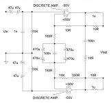
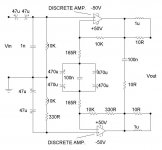
This is on the face of it, a good idea, as one would need only +/-50V rails to generate ~450W into 8ohms...alleviating transistor SOA problems.
The basic circuit of post #1 (with a differential gain of ~21 Andy-c), should in principal, achieve this objective....
However, having a differential input, means that the preceding line-level preamp would have to generate a double-ended output, which on reflection,... ....is unnecessary, as the preamp. is hardly likely to have SOA difficulties......
Of course such a preamp. could, it might be argued, enhance system CMRR.....this however is not a significant problem.
So....out with the differential input,...HELLO single-ended input...
...the oscillation problem was narrowed down to the rather shody feedback connections, (a stereo amp.was used to test the concept)......stillsome parasitic, but reckon a properly laid out prototype pcb should sort this out..
.......the idea was to design a fully differential power amp.
This is on the face of it, a good idea, as one would need only +/-50V rails to generate ~450W into 8ohms...alleviating transistor SOA problems.
The basic circuit of post #1 (with a differential gain of ~21 Andy-c), should in principal, achieve this objective....
However, having a differential input, means that the preceding line-level preamp would have to generate a double-ended output, which on reflection,...
....is unnecessary, as the preamp. is hardly likely to have SOA difficulties......Of course such a preamp. could, it might be argued, enhance system CMRR.....this however is not a significant problem.
So....out with the differential input,...HELLO single-ended input...
...the oscillation problem was narrowed down to the rather shody feedback connections, (a stereo amp.was used to test the concept)......stillsome parasitic, but reckon a properly laid out prototype pcb should sort this out..
Attachments
stax...
got those stax schematics jam... ...?
jam said:Fred,
I think that Mike also wants to drive the amplifier with a single ended input by grounding the - input (maintaining a brideged topology). Stax used approach years ago in some of their amps.
Regards,
Jam
P.S. Then again I could be wrong.......
got those stax schematics jam...
...?
While this method of bridging looks the best on paper, it usually results in a power oscillator.
Is the ± 50V power supply common for both halves? Dual mono supplies is no-no for a bridge amplifier, the ground currents are enormous. Strap the supplies together.
Try re-arranging the output zobels and the feedbck loop like this:
http://www.mif.pg.gda.pl/homepages/tom/files/simp200W.gif
The feedback loop cannot be DC coupled as yours is, plus the high end on the right half must be rolled off. The only ground is for the input off-set current .
When you are ready to give up and just want it to work, change it to this:
http://sound.westhost.com/project20.htm
djk said:"Here's a schematic of a Sumo Amp. May be of some help."
That is a Circlotron, not applicble here.
It is worthwhile to note that the gains of each half are different.
How is that the gain is different ? They seem the same to me.
mcp said:Mike
Here's a schematic of a Sumo Amp. May be of some help.
thanks mcp..
djk said:While this method of bridging looks the best on paper, it usually results in a power oscillator.
With the last modification, in post # 21, i have seen no evidence of inclination to full scale oscillation...just minute parasitic, that appears and reappears as i move the feedback wires around....its a 'cut-and-paste' job on what is essentially a stereo amp. should improve with a bespoke pcb...fingers crossed...
djk said:Is the ± 50V power supply common for both halves? Dual mono supplies is no-no for a bridge amplifier, the ground currents are enormous. Strap the supplies together.
Try re-arranging the output zobels and the feedbck loop like this:
http://www.mif.pg.gda.pl/homepages/tom/files/simp200W.gif
Indeed the the supply is common to both halves in this experimental set-up, with star grounding for each half...
djk said:The feedback loop cannot be DC coupled as yours is, plus the high end on the right half must be rolled off. The only ground is for the input off-set current .
i am not sure i understand......but the feedback loops to each half are infact AC coupled.....
...each half retains 100% DC negative feedback, which ensures that the outputs of each half default to a nominal zero DC for no input signal....
...can you clarify 'the high end on the right half must be rolled off'?
Thanks for your help in advance...

djk said:
When you are ready to give up and just want it to work, change it to this:
http://sound.westhost.com/project20.htm
yes i have used this....but somehow i figured i would try something 'new'......
djk said:It is worthwhile to note that the gains of each half are different. [/B]
the gains in each half are indeed different if it only accepts single-ended signals, but would have to be identical if only a balanced input is envisaged. see pg.21-22
http://users.ece.gatech.edu/~mleach/ece4435/chap01.pdf
FDPA
Mikek,
As far as I can see, this is a differential power instrumentation amp. The gain in each half is the 10k feedback against the common resistor which (in original schematic) was 2 x 165 Ohms. I see no reason why there is a need for the 330 Ohms in series with the 10k's. The 2 inputs are independent, and can be driven both, or only one and the other grounded. Also, the 2 165 Ohms resistors in the common part can be just one 330 Ohms.
Jan Didden
hi janneman
It would appear you haven't read the thread from the beginning...the resistor values for the fig. in post#1 are correct only if the amp. accepts differential inputs.....
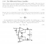
...if the amp. accepts only single-ended inputs, then the gains in the two halves have to be different...see text and fig. below:
as for 330=165+165, i didn't have enough 330R in my bin...
janneman said:Mikek,
As far as I can see, this is a differential power instrumentation amp. The gain in each half is the 10k feedback against the common resistor which (in original schematic) was 2 x 165 Ohms. I see no reason why there is a need for the 330 Ohms in series with the 10k's. The 2 inputs are independent, and can be driven both, or only one and the other grounded. Also, the 2 165 Ohms resistors in the common part can be just one 330 Ohms.
Jan Didden
It would appear you haven't read the thread from the beginning
...the resistor values for the fig. in post#1 are correct only if the amp. accepts differential inputs........if the amp. accepts only single-ended inputs, then the gains in the two halves have to be different...see text and fig. below:
as for 330=165+165, i didn't have enough 330R in my bin...
Attachments
slew?
There is an interesting relationship between bridged amps., with unity gain output stages, and single ended amps. with gain built into their output stage.
slew is increased.....
http://diyaudio.com/forums/showthread.php?s=&threadid=14482
for the design in post#31, (or indeed any other bridged setup), each amp. has a slew ~45V/uS, and is required to swing ~+/-40V....which leads to a net swing across the load of+/-80V.....which in turn means you have an effective slew rate between the two differential outputs of ~90V/uS......
I don't know what a Circlotron is but it says quite clearly that it is a Dual Differential 70Watts Class A Sumo. Possibly by James Bongiorno, has is thumbprint on it. As for whether it is applicable, examine the concept closely.That is a Circlotron, not applicble here.
It is worthwhile to note that the gains of each half are different.
By the way, the gains are not unequal. they are both at 11x because one is positive driven while the other is negative.
mcp said:
By the way, the gains are not unequal. they are both at 11x because one is positive driven while the other is negative.
...see post #33...
mcp said:
I don't know what a Circlotron is but it says quite clearly that it is a Dual Differential 70Watts Class A Sumo. Possibly by James Bongiorno, has is thumbprint on it. As for whether it is applicable, examine the concept closely.
Yes it is indeed a Bongiorno design...see..
http://patft.uspto.gov/netacgi/nph-...0&s1=4229706.WKU.&OS=PN/4229706&RS=PN/4229706
mikek,
I just do not know what you are trying to do. Would you like to build a perfect hi-end amplifier (with perfect sound as well) or to solve an "interesting" circuit problem, regardless the sonic result? Unfortunately I did not see many people trying to solve both.
Pavel
I just do not know what you are trying to do. Would you like to build a perfect hi-end amplifier (with perfect sound as well) or to solve an "interesting" circuit problem, regardless the sonic result? Unfortunately I did not see many people trying to solve both.
Pavel
- Status
- This old topic is closed. If you want to reopen this topic, contact a moderator using the "Report Post" button.
- Home
- Amplifiers
- Solid State
- Fully differential power amp.....Help.