Yep, it would be. But then you wouldn't learn anything. Nothing wrong with doing both...I'd bet good money that trying to build and sort out a new, reliable Wien bridge oscillator is more work than just fixing whatever is wrong with your commercial function generator.

True - but despite the thread's inaccurate name the OP was referring to a sine wave oscillator - something quite different than a function generator that will output a sine.eadbelly - Inexpensive function generators create 1% THD sine waves by clamping a triangle wave. Building an actual low-distortion sine wave oscillator was too hard/costly.
Ed
Except in OP's case it's a cheap function generator that may not have worked all that well to begin with so getting a better generator might be the ticket.I'd bet good money that trying to build and sort out a new, reliable Wien bridge oscillator is more work than just fixing whatever is wrong with your commercial function generator.
The HP 239 and 339 are certainly good and so are the 3312A and 33120A.
Tom
Seems like a bit of hair-splitting there. I agree that there is a difference, but the sine output of a decent function generator, including the HP 3312A and 33120A actually provide quite good performance. Typically around -95 dBc THD at 1 kHz, 2 V RMS for the ones I've tested.True - but despite the thread's inaccurate name the OP was referring to a sine wave oscillator - something quite different than a function generator that will output a sine.
For a high-purity sine wave, consider using a good external sound card. Focusrite makes some good ones that are quite affordable.
Tom
a. Buying a HP or branded function generator new or used is outside my budget.
b. I did try to clean up my China Function generator and it did clean up. But no where near where I could use it to test THD of the amps and preamps I am building.
c. I did consider buying a sound card the Behringer UCA222 was the one I was going to buy. But a day before pulling the triger on that one. I read an article that said it was a POS not worth using.
What the DIY amature community needs is a simple easy to build low THD sine wave generator. Yes your right this concept is what setup HP my friend did mention this.
I still have not heard a decent answer to how do I select the best transistor for my audio circuit. So I figured if I could measure THD and noise floor it would be a good start.
A friend did gift me a FIIO K5 Pro. When he upgraded. But I cant get it to work with REW or ARTA because it does not have an input that shows up in windows. My dats V3. On the other hand does show both input and output. Maybe I should look at using that.
I use Right Mark audio software to measure audio circuits, it provides lots of information. THD, fr response, intermodulation, fr spectrum, phase, enough for me. And its free, just like REW. I use REW mostly for speakers. Both free. Both generates their own signal.
What is it you want? Perhaps people would help you if you actually tell them what you want. For once.
What is it you want? Perhaps people would help you if you actually tell them what you want. For once.
Attachments


Here is link for free download.
https://audio.rightmark.org/index_new.shtml
https://audio.rightmark.org/index_new.shtml
That could be because that's a really broad question. It's sorta like asking, which car should I buy? Kudos for wanting to measure things, though.I still have not heard a decent answer to how do I select the best transistor for my audio circuit.
Tom
Since you asked.I use Right Mark audio software to measure audio circuits, it provides lots of information. THD, fr response, intermodulation, fr spectrum, phase, enough for me. And its free, just like REW. I use REW mostly for speakers. Both free. Both generates their own signal.
What is it you want? Perhaps people would help you if you actually tell them what you want. For once.
I want the ability to see how changing components and circuits impact THD / Noise Floor. / Noise / output. I want to play with this.
Like Rods P3A amp. I have 4-5 different PCBs all built around the same schematic. So far I have built 3 boards. All with the same components. Testing should show me which board is the best. Once I know that. The next step is to start changing transistors and other components to see which improves the benchmark numbers and which ones degrade.
I did some double blind tests with a group of friends. One channel was with one driver transistor and the other with another.
All could figure out the difference. All had their prefered channel. The results were split down the middle.
So I really do not trust the human ear when it comes to deciding.
My day job is building race engines. Here its simple. Put it on a Dyno. Get the most power under the curve without over heating or deto. And its a wrap. Im looking to do something similar for my Preamps and Amps.
My focus is only on Class A and Class A/B as those are the systems I imprinted on as a kid in the 70s.
I also need to figure out why nothing I have built sounds as good or is as efficient as a quasi complementary. Amp built in the 80s. By efficient I mean voltage at transformer vs output to speakers without clipping.
Can you share the parameters you test for and how you do it. I will check youtube for any guides.Here is link for free download.
https://audio.rightmark.org/index_new.shtml
Maybe that amplifier was not very good. Usually, hearing a difference is a sign of a not-so-great amplifier.I also need to figure out why nothing I have built sounds as good or is as efficient as a quasi complementary. Amp built in the 80s.
IME, the amplifier parameter most responsible for audible differences is output impedance. A few tenths of an ohm will audibly affect the response of the speaker crossover.
I suggest starting with simulation. Simulators are sufficiently accurate to identify amplifier faults that would be audible.
Ed
Last edited:
No. Since I already did that in previous post. Even attached pictures listing all the parameters.Can you share the parameters you test for and how you do it. I will check youtube for any guides.
If the OP (or someone else) wants build a simple (and not that bad) bulb-stabilized oscillator...
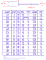
In '90s AVT was selling diy-kit "Laboratory audio-frequency sine wave generator". In attached article the author describes this circuit and the design process. Foreign language, but diagrams and tables are "international".
Important things from this article:
In '90s AVT was selling diy-kit "Laboratory audio-frequency sine wave generator". In attached article the author describes this circuit and the design process. Foreign language, but diagrams and tables are "international".
Important things from this article:
- op-amp with higher Iout (NE5532) is better for stability
- hi-V low-I bulbs are better than others
- higher Ub (24V) give better parameters
Attachments

- Home
- General Interest
- Everything Else
- Function Generator with light bulb