And so it goes.
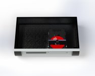
OK so 3D CAD is fun and the process is informative. I now understand why folks get teary eyed over mech quality, or lack thereof. However, it's also a really good for putting things in a box before any proper destruction has begun.
But some actual, useful, fiddling has intruded and I decided to look properly at the FCD's valve output stage. It's not an X10-D well not exactly... (yes I'm well aware that the x10-d is electrically unremarkable, but its a reference - don't shoot me)
No voltage doubler, on this board at least, and a different (than the X-10D) approach to the B+ Supplies and grounding of the first valve section. Also it does have a relay grounding the output during start up but imagine that in the schematic if you need to
The PSU board needs more disassembly than I want to commit to, before I have a plan that reaches past tomorrow. I'll get there no doubt.
Next step is to measure some voltages I suppose?
Andy
OK so 3D CAD is fun and the process is informative. I now understand why folks get teary eyed over mech quality, or lack thereof. However, it's also a really good for putting things in a box before any proper destruction has begun.
But some actual, useful, fiddling has intruded
and I decided to look properly at the FCD's valve output stage. It's not an X10-D well not exactly... (yes I'm well aware that the x10-d is electrically unremarkable, but its a reference - don't shoot me)No voltage doubler, on this board at least, and a different (than the X-10D) approach to the B+ Supplies and grounding of the first valve section. Also it does have a relay grounding the output during start up but imagine that in the schematic if you need to
The PSU board needs more disassembly than I want to commit to, before I have a plan that reaches past tomorrow. I'll get there no doubt.
Next step is to measure some voltages I suppose?
Andy
Attachments
So last one for a bank holiday
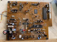
Lets 'take a dive' into the FCD main board, which I just realised (slowpoke) was easier to get to than I thought by just cutting the optical SPDIF wires. Not using them again anyway
Then a genuine LOL which I thought I'd share
See photo, yeah in todays money a £3K unit.... So Normally I have the greatest of respect for past engineers and the limitations of their time, but scrubbing out chip numbers 'so no one can tell' is the equivalent of kindergarten!
Funny - because its SO bad - automatic 'Hall of shame' for you! No matter whom you may be (and perhaps whatever you created next)
I will admit to a soft spot for M.F. as this thread attests, but 'FFS' did they employ five year olds? Was that allowed in the 90's?
Still chuckling