Guesstimating from the apparent period of the ripple, that may be an issue around 1800 Hz. For your application, that seems unlikely to be a real world problem even if there's not something else wrong in the model.are the small ripples in the first graph a problem
It's like worrying about a metal cone woofer's nasty midrange breakup when you're only using the driver for low bass.
Thanks for your reply!
Guesstimating from the apparent period of the ripple, that may be an issue around 1800 Hz. For your application, that seems unlikely to be a real world problem even if there's not something else wrong in the model.
It's like worrying about a metal cone woofer's nasty midrange breakup when you're only using the driver for low bass.
@kazap: I tried to download the hornresp txt file from loudspeakerdatabase.com but it seems the downloaded file doesn't contain a complete set of pameters:
SB SB17NAC35-8
Sd=118.0
Bl=6.2
Cms=1680.0E-06
Rms=0.5
Mmd=14.2
Le=0.15
Re=5.7
Pmax=120.0
Xmax=5.5
LossyLe=0
So Qes and Qms are missing and some other important parameters? So that's why I just insert them manually through the Imput Parameters screen.
I discovered that I made a mistake in the Input Wizard when simulating a flat open baffle: I accidenally seleted H-frame open baffle as I was "programmed" to select this option during the many H - and U frame simulations...
So now comes the question which design to go for. I have no idea how audible the 'less clean' impulse response, group delay and phase graph will be compared to the flat open baffle design. If I'm correct, the flat open baffle desigh has the best impulse, group delay and phase graphs. Only max SPL is better for U and H baffle designs. (in my simulations +6 dB) But I can compensate for that by adding more drivers, for instance 8 instead of 6 per channel, although this gives only +3 dB gain so the price per dB is steep. This makes the physical length larger which is welcome for larger listening positions.
Comparison of 20 cm wide flat open baffle to 20 cm wide and 2*10 cm deep H baffle:
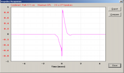
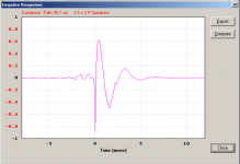
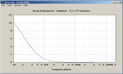
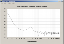
So I made many simulations but I tend to go for a simple flat baffle design and I can easily make two of them and adding some temporarily mounted wings on one of them to compare them. Then I can even compare U and H frames to a flat open baffle.
Would this be a good idea? If so, I have to select a driver. I think the drivers which I found to match the parameters given by Calvin are only 3 and they seem to be comparable in max spl, the Dayton RS180-4 gives a little bit (+1dB) more SPL than the SB17NAC35-8. I attached the flat baffle and H baffle simulations, all 20 cm baffle width and for the H baffle 2*10 cm depth.
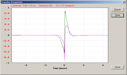
The only clear difference I see between the Dayton and SB Acoustics is the impulse response: (green = SB, purple = Dayton)
SB SB17NAC35-8
Sd=118.0
Bl=6.2
Cms=1680.0E-06
Rms=0.5
Mmd=14.2
Le=0.15
Re=5.7
Pmax=120.0
Xmax=5.5
LossyLe=0
So Qes and Qms are missing and some other important parameters? So that's why I just insert them manually through the Imput Parameters screen.
I discovered that I made a mistake in the Input Wizard when simulating a flat open baffle: I accidenally seleted H-frame open baffle as I was "programmed" to select this option during the many H - and U frame simulations...
So now comes the question which design to go for. I have no idea how audible the 'less clean' impulse response, group delay and phase graph will be compared to the flat open baffle design. If I'm correct, the flat open baffle desigh has the best impulse, group delay and phase graphs. Only max SPL is better for U and H baffle designs. (in my simulations +6 dB) But I can compensate for that by adding more drivers, for instance 8 instead of 6 per channel, although this gives only +3 dB gain so the price per dB is steep. This makes the physical length larger which is welcome for larger listening positions.
Comparison of 20 cm wide flat open baffle to 20 cm wide and 2*10 cm deep H baffle:


So I made many simulations but I tend to go for a simple flat baffle design and I can easily make two of them and adding some temporarily mounted wings on one of them to compare them. Then I can even compare U and H frames to a flat open baffle.
Would this be a good idea? If so, I have to select a driver. I think the drivers which I found to match the parameters given by Calvin are only 3 and they seem to be comparable in max spl, the Dayton RS180-4 gives a little bit (+1dB) more SPL than the SB17NAC35-8. I attached the flat baffle and H baffle simulations, all 20 cm baffle width and for the H baffle 2*10 cm depth.
The only clear difference I see between the Dayton and SB Acoustics is the impulse response: (green = SB, purple = Dayton)

Last edited:
The Hornresp driver txt file contains all the information required. Hornresp uses physical parameters rather than Thiel/Small Parameters to define the driver attributes. Qes and Qms can be calculated from the physical parameters, or they can be used with the rest of the Thiel/Small parameters to calculate the physical parameters seen in the Input Window. This is what the Hornresp Driver Parameter screen does for you.@kazap: I tried to download the hornresp txt file from loudspeakerdatabase.com but it seems the downloaded file doesn't contain a complete set of pameters:
...So Qes and Qms are missing and some other important parameters?
I would not look at the impulse response calculated from the Maximum SPL curve as it is rather meaningless. I would look at the frequency response curve and impulse response after you have applied whatever EQ and crossover you will be using.I have no idea how audible the 'less clean' impulse response, group delay and phase graph will be compared to the flat open baffle design. If I'm correct, the flat open baffle desigh has the best impulse, group delay and phase graphs. Only max SPL is better for U and H baffle designs.
Can you post screen shots of your Input Parameters window for the H-frame? Or you could also export it as a Hornresp record from the file menu while viewing the Input Parameters window. I am unable to reproduce your Impulse results and am trying to understand it. Oh, also what version of Hornresp are you using?
The difference you are seeing is just due to the higher voice coil inductance of the Dayton. Once you have the crossover in place this difference in the impulse response will not be seen.The only clear difference I see between the Dayton and SB Acoustics is the impulse response: (green = SB, purple = Dayton)
The Hornresp driver txt file contains all the information required. Hornresp uses physical parameters rather than Thiel/Small Parameters to define the driver attributes. Qes and Qms can be calculated from the physical parameters, or they can be used with the rest of the Thiel/Small parameters to calculate the physical parameters seen in the Input Window. This is what the Hornresp Driver Parameter screen does for you.
I would not look at the impulse response calculated from the Maximum SPL curve as it is rather meaningless. I would look at the frequency response curve and impulse response after you have applied whatever EQ and crossover you will be using.
Can you post screen shots of your Input Parameters window for the H-frame? Or you could also export it as a Hornresp record from the file menu while viewing the Input Parameters window. I am unable to reproduce your Impulse results and am trying to understand it. Oh, also what version of Hornresp are you using?
The difference you are seeing is just due to the higher voice coil inductance of the Dayton. Once you have the crossover in place this difference in the impulse response will not be seen.
Thanks again for your extensive reply! I was already questioning myself why the inserted parameters were sometimes changing slightly, but this explains it.
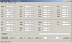
In the attachement I put an export file of the H-frame simulation if I'm correct. I made a screenshot of the Input Parameters screen as well:
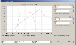
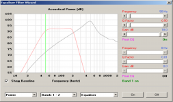
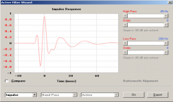
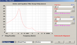
About the equalizing and crossover: I guess this can be arranged by using the Filter wizard => Active option where I can insert a Low pass filter, for instance 48 dB/oct @ 250Hz, and a High pass filter @45Hz 48 dB/oct for limiting driver excursion and Filter wizard => equalizer option where I can compensate for dipole roll-off. (I just inserted some quick test values to get an idea of how this effects ipulse response and group delay).
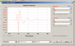
Some screenshots of the Filter wizard:
Attachments
Last edited:
S2 should be 400 not 399.In the attachement I put an export file of the H-frame simulation if I'm correct.
S2 should be 400 not 399.
Thanks again for your help!
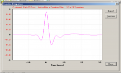
I still have some things which remain unclear, for instance, when I view the impulse response in the Filter wizard I see a different graph compared to the impulse response graph from the tools => impulse response menu. If I'm correct, both should be equal and display the impulse response of the complete system which is in my case the active section (high + low pass filters) and the equaliser section (1 peak eq) together with the loudspeaker? (I pushed the "On" button in the Filter wizard to apply the filters to the different graphs / result.
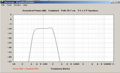
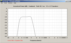
Acoustical power graph after applying the filters to the H-frame baffle:
Phase response from the Filter wizard:
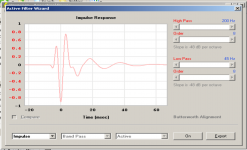
Phase response from the Tools => impulse response menu:
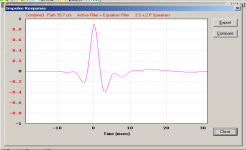
Any idea why the last two graphs differ?
(I updated the Hornresp data file and attached this updated version in this message)
Attachments
Last edited:
The chosen filters have reduced the power response to an impractical level (-10dB).Acoustical power graph after applying the filters to the H-frame baffle:
The first impulse response is for single loudspeaker, the second impulse response is for an array of 3S x 2P loudspeakers.Any idea why the last two graphs differ?
EDIT - On further checking something doesn't seem quite right. I need to investigate further.
Last edited:
I found the problem, it will be fixed in the next update. The impulse response results will then be the same.EDIT - On further checking something doesn't seem quite right. I need to investigate further.
Thanks for your message and sorting out the problem. Just to be sure: in the current version the first response from post #107 is for a single speaker, the second for multiple (3S x 2P) speakers. In the next updated version the first graph (impulse response in filter wizard) will take into account the multiple speakers selected by the user?I found the problem, it will be fixed in the next update. The impulse response results will then be the same.
The current version already does that. It turned out that the results were different due to a bug, rather than being caused by a different number of speakers. The first impulse response you posted is correct, the second one is not.In the next updated version the first graph (impulse response in filter wizard) will take into account the multiple speakers selected by the user?
When the update is released (hopefully shortly), the results for your two test examples will be as shown in the attachments.
Attachments
The Hornresp update has now been released:
https://www.diyaudio.com/community/threads/hornresp.119854/page-638#post-7040869
https://www.diyaudio.com/community/threads/hornresp.119854/page-638#post-7040869
I will update my version soon. Thanks again for your effort!The Hornresp update has now been released:
https://www.diyaudio.com/community/threads/hornresp.119854/page-638#post-7040869
Hi again,
it has been some time since I posted a message in this topic, but after some absence and not listening to my peerless sls-12 OB sub, I started using it again and this time I don't hear a clear sound quality degradation anymore. Mainly I experience extended LF energy and I just tuned it my preference with my ears rather than using measurements to tune it to the correct level.
So I'm still interested in building an OB line array woofer consisting of multipe drivers. I got some advice for suitable drivers by Calvin: the Dayton RS-180. I found some suitable drivers according to Calvins recommended specs: SB16PFC25-8 and SB17NAC35-8.
As I need a lot of drivers even for 1 channel to get enough sound pressure for these smaller drivers it will be an expensive experiment.
I made many simulations using Hornresp, the latest simulations have all eq filtering included. My observation, assumed I made no errors in my simulations, is that the results (impulse response, group delay) all look very similar between the different drivers when using the same type of baffle (I mainly simulated plain open baffles as these show best IR + GD and "worst" SPL.
Both the Dayton RS-180 and SB Acoustics SB17NAC35-8 are quite "expensive" compared to the SB Acoustics SB16PFC25-8: around 70 euros, whereas the SB16PFC25-8 is around 33 euros. The SB16PFC25-8 has less Xmax and gives lower SPL, but the price per SPL is still the lowest: if I use 12 (!) SB16PFC25-8 drivers per channel I still get 4 dB output more than using 6 of the other drivers and the total price is still (just a bit) lower. The only drawback is the panels will get much taller, at least around 2 meters tall.
Any ideas whether or not this looks like a viable setup / driver for testing / purchasing? Should I start with "only" lets say 4 drivers to test at low levels to keep initial cost low and after testing buy more drivers? (the driver unfortunately seems to be discontinued...)
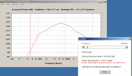
These are some simulaton plots I made with 3*4 the SB16PFC25-8 drivers mounted in a 20 cm wide baffle:
driver datasheet: https://sbacoustics.com/wp-content/uploads/2020/11/6in-SB16PFC25-8-OEM-only.pdf


keep initial cost low
To keep your budget on track Id suggest maybe looking into affordable low spec drivers? These drivers have weaker motors with higher Qts and lower peak power capacity. Thats a match for OB. Lower Xmax gets made up with multiples. Some say cheap drivers running well within Xmax at low displacement can even sound pretty good.
If you post around you might find a local who has dozens of drivers languishing on a shelf to sell?
@kazap: thanks for your suggestion! It seems the affordable SB16PFC25-8 is discontinued so not sure if I can get 24 pieces at all.
I'm not sure if I want higher Qts drives as the ones I already have (Peerless SLS-12) sound ok but as stated by Calvin lower Qts drivers could sound better:
https://www.diyaudio.com/community/...atic-panels-advice-needed.375319/post-7015980
I'm not sure if I want higher Qts drives as the ones I already have (Peerless SLS-12) sound ok but as stated by Calvin lower Qts drivers could sound better:
https://www.diyaudio.com/community/...atic-panels-advice-needed.375319/post-7015980
I still have another, maybe silly, question about the Dayton RS-180 (4 ohms version). The datasheet states:
"Excellent car audio midrange/midbass".
To me car audio gear always sounds a bit more directed towards SPL rather than sound quality (although this is a generalisation). But I would think the Dayton RS180-4 looks like a good quality hifi driver? The driver seems to have the best specs as xmax is a little higher than the SB17NAC35-8 which I also consider. Sd is also higher than the SB17NAC35-8. Do you have any idea if the car audio thing tells anything about quality of the driver?
Do you have any idea if the car audio thing tells anything about quality of the driver?
Id be more interested in the specs, finding independent measurements and user impressions as a guide.
I've used the RS180P-4 (paper cone version) in a couple different prototypes with passive radiators and like them overall. One of these was with GRS planars for 500 Hz and up. That doesn't guarantee that you'll like them in your application obviously, but for me they worked well.
I think the car audio angle is just a way to increase potential uses for the driver. I doubt they made any compromises specific to that application. Since they work pretty well in smaller enclosures, car audio is just a natural place for them to suggest use.
Car audio is almost split in two different camps anymore. There are people that pursue SPL without much regard for anything else, but there are also people that are seriously pursuing sound quality. Of course there's overlap for some, but that was more common in the early days when IASCA was the major sanctioning body and tried harder to blend the two.
Thanks for the link!Id be more interested in the specs, finding independent measurements and user impressions as a guide.
- Home
- Loudspeakers
- Planars & Exotics
- My newest pair of DIY electrostatic panels, advice needed

