Though on further reading this might not be required in mine because I am using the ecdesigns 100hz DEM - sorry don't mean to threadjack
First time I've come across that Grundig mod for TDA1541A - thought I'd captured it all in my Arcam Alpha board-based frankenDAC. Will have to give it a try.
I have these 2 Magnavox CDM4/TDA1543 machines on the workbench:
For both of these machines the buttons to hold down for service mode are:
[SEARCH >] [PAUSE] [REPEAT].
This matches the service manual for the Philips CD582, but does not match the Philips manual for CD480/482.
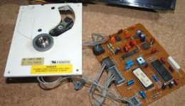
I confirmed one CDM4 transport has a bad laser diode. There is no measurable IR output. The Iop (actual laser diode current) is >100mA regardless of where the trimpot is set.
The other CDM4 has Iop=60mA after calibrating the trimpot for 50mV across 4K7 resistor. Measured IR light intensity is 100uW after this adjustment.
Now I'm troubleshooting the CDB480 main PC board. It won't rotate the spindle motor correctly. I suspect an issue with the servo controller. I'll compare it to the functional PC board of the CD2000. They seem identical in circuit design. However PC the board layouts are slightly different. All electrolytics have already been checked/replaced. Also the grounding jumper vias and other soldered connections have been checked.
-EB
- CD2000
- CDB480 (similar to Philips CD480/482)
For both of these machines the buttons to hold down for service mode are:
[SEARCH >] [PAUSE] [REPEAT].
This matches the service manual for the Philips CD582, but does not match the Philips manual for CD480/482.
I confirmed one CDM4 transport has a bad laser diode. There is no measurable IR output. The Iop (actual laser diode current) is >100mA regardless of where the trimpot is set.
The other CDM4 has Iop=60mA after calibrating the trimpot for 50mV across 4K7 resistor. Measured IR light intensity is 100uW after this adjustment.
Now I'm troubleshooting the CDB480 main PC board. It won't rotate the spindle motor correctly. I suspect an issue with the servo controller. I'll compare it to the functional PC board of the CD2000. They seem identical in circuit design. However PC the board layouts are slightly different. All electrolytics have already been checked/replaced. Also the grounding jumper vias and other soldered connections have been checked.
-EB
Something I haven't been able to locate yet are exact schematics for the (nearly identical) Magnavox CDB480 and CD2000 models.
I'm currently using a Philips CD480 service manual.
It is close to matching my units, but it shows SAA7220/TDA1541 rather than TDA1543 alone.
Fortunately it does show the SAA7210 for the digital decoder. This is what my units contain.
Magnavox CDB480 corresponds to Philips CD480
Philips has a "combined" service manual for the CD480/CD482 models (I'm using it)
I saw a post mentioning 3 versions of the Philips CD482 model:
That suggests I have the CD482/10 version.
I also saw a Magnavox CDB492 / Philips CD492 mentioned. But I haven't found any service manuals for either of those models.
-EB
I'm currently using a Philips CD480 service manual.
It is close to matching my units, but it shows SAA7220/TDA1541 rather than TDA1543 alone.
Fortunately it does show the SAA7210 for the digital decoder. This is what my units contain.
Magnavox CDB480 corresponds to Philips CD480
Philips has a "combined" service manual for the CD480/CD482 models (I'm using it)
I saw a post mentioning 3 versions of the Philips CD482 model:
- CD482/00 IC chips: SAA7210/SAA7220/TDA1541
- CD482/10 IC chips: SAA7210/TDA1543
- CD482/30 IC chips: SAA7310/TDA1543
That suggests I have the CD482/10 version.
I also saw a Magnavox CDB492 / Philips CD492 mentioned. But I haven't found any service manuals for either of those models.
-EB
I’m still around but (temporarily) switched to repairing/restoring a bunch of integrated amplifiers and power amplifiers which are in my collection.
I still plan to complete the restoration process and then listen to my Mission PCM4000 and my Proton CD player.
My current “daily listening” disc players are a Denon DCM-320 5-disc changer in my living room system and a single-disc Sony DVP-NS775V in the bedroom. The Denon unit sounds incredibly good on every disc I put into it. Many people have little regard for CD changers but this one is exceptional. I haven’t yet identified why it sounds as great as it does. It will be fun to compare it with the Philips-based CD players after I finish restoring them. I hope to do that in the very near future.
-EB
Hi brother , I m Jacky from Singapore, I have a Philips cd850 cdp , it spindle motor spinning non stop when power was on , what component was failed inside ,need your great helps..I’m still around but (temporarily) switched to repairing/restoring a bunch of integrated amplifiers and power amplifiers which are in my collection.
I still plan to complete the restoration process and then listen to my Mission PCM4000 and my Proton CD player.
My current “daily listening” disc players are a Denon DCM-320 5-disc changer in my living room system and a single-disc Sony DVP-NS775V in the bedroom. The Denon unit sounds incredibly good on every disc I put into it. Many people have little regard for CD changers but this one is exceptional. I haven’t yet identified why it sounds as great as it does. It will be fun to compare it with the Philips-based CD players after I finish restoring them. I hope to do that in the very near future.
-EB
Attachments
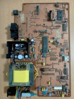
Hi, start by replacing all the marked axial electrolytics. You can replace them all by 22uF/25V, despite the originals might have other values. Is it spinning faster than normal or maybe reverse? A missing clock signal might also be the cause, here with the CD850, its coming from the DAC doughter booard, so check there too.
Attachments

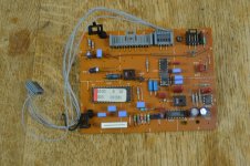
according page 6-1 of CDM-2 service manual (also for CDM-4) which is additional necessary as supplement for a lot of models, there are a lot of different associated servo boards.
This PSB's can be recognized by the 4-digit number on the attached sticker mostly glued on the surface of TDA5708 (check out the attachments).
Unfortunately from several PCB's sticker with this number isn't longer to find.
The service manual version under
https://www.hifiengine.com/manual_library/philips/cdm-2.shtml
also to find under
https://elektrotanya.com/philips_cdm-2_cd-mechanism_sm.pdf/download.html
includes the following PCB versions:
1) static version of CDM-2, 5725 and 5768
2) dynamic version of CDM2, 5826 and 5827
But there are many other PCB-Versions, 5886, 5888, 6127 and 6105 are some additional examples.
Because the version 5886 is in use on Philips CD660 and CD670 and the CD660 service manual refers to the above mentioned service manual for the CDM-2 I guess, there is at least one upgrade resp. supplement to the CDM-2 service manual.
Who can upload this supplements (for me most important is the version "6105" used in Micromega SOLO first series) ?
Thank you very much.
Attachments
-
 5897 servo.jpg186.8 KB · Views: 649
 -
 Cambr. Audio CD2 servo CDM4-11.jpg150.8 KB · Views: 510
 -
 5888 servo CDM2-29 cambr. audio CD3.jpg65.7 KB · Views: 459
 -
 CDM2-10.jpg10 KB · Views: 382
 -
 CDM4-31 Servo board Sherwood CDP301R-IV.jpg97.2 KB · Views: 577
 -
 CDM2-10-Servo board Sherwood CDP301R-II.jpg113.2 KB · Views: 336
 -
 5886 servo mission PCM-II.jpg101.3 KB · Views: 485
 -
 CDM2-10-Servo board Sherwood CDP301R.jpg34.1 KB · Views: 634
 -
 CDM4-31-005-500pix.jpg55.8 KB · Views: 355
 -
 CDM4-31-004-500pix.jpg33.4 KB · Views: 455
Last edited:
Problem is, that I have Micromega SOLO with faulty servo board "6105" for CDM-4 and I need therefore schematic and adjustment procedure.I have read your question several times on several threads and I still do not understand what you are looking for / want? or even why.
I must have between 30 and 40 players based on CDM (from zero to pro)
what is your problem, what are you looking for? ,it's not clear .
SM for Philips CD660/670 (partly same CDM drive with this servo board inside) refers to the separat available CDM-2 service-manual
This I have and there four different versions of servo boards described on page 6-1 but no version, what I looking for.
I need service information for the version "6105" (maybe "5886" is similar) and a Philips/Marantz CD Player, where the "6105" servo board is in use.
To make long story short I need a service manual for my Micromega SOLO, but nobody can help.
Therefore a short story is to extend and making complicate to explain my problem.
Check out page 6-1 in CDM-2 service manual - my estimate is, that there are a lot of supplements for additional servo boards exist from Philips like the mentioned.
This supplements I want to have for service and maintenance - not only for my Micromega.
Hi weissi , already replaced those capacitors , the problem was when on the player ,the spindler motor spinning non stop ,very fast speed , the missing clock signal from the dac?I disconnect the cable to the dac board still the same problem.haha..Hi, start by replacing all the marked axial electrolytics. You can replace them all by 22uF/25V, despite the originals might have other values. Is it spinning faster than normal or maybe reverse? A missing clock signal might also be the cause, here with the CD850, its coming from the DAC doughter booard, so check there too.
is it urgent or not?Problem is, that I have Micromega SOLO with faulty servo board "6105" for CDM-4 and I need therefore schematic and adjustment procedure.
SM for Philips CD660/670 (partly same CDM drive with this servo board inside) refers to the separat available CDM-2 service-manual
This I have and there four different versions of servo boards described on page 6-1 but no version, what I looking for.
I need service information for the version "6105" (maybe "5886" is similar) and a Philips/Marantz CD Player, where the "6105" servo board is in use.
To make long story short I need a service manual for my Micromega SOLO, but nobody can help.
Therefore a short story is to extend and making complicate to explain my problem.
Check out page 6-1 in CDM-2 service manual - my estimate is, that there are a lot of supplements for additional servo boards exist from Philips like the mentioned.
This supplements I want to have for service and maintenance - not only for my Micromega.
I ask you this because I can open all my cdm4-based readers and see if the card is present there and if so, the service manual that goes with the model will follow.
FYI I also have a broken Micromega (based on cdm2) and there is no service manual.
FYI, I've never failed to repair a cdm4-based player, but "custom" models like Micromega can be difficult to troubleshoot.
PS: don't hesitate to send me a pm if it's too long, I have a very relative notion of time...
In the meantime I have found service-manuals for the servo boards 5886 (1K for focus offset) and 6105 (4K7 for focus offset) both boards are in use here:
1) B&O Beogram CD-4500, CD-3500, CD-5500 and CD-6500
https://www.vintageshifi.com/repert...ng-Olufsen-Beogram_CD-4500-Service-Manual.pdf
2) Revox B126
https://www.hifiengine.com/manual_library/revox/b126.shtml
I think, the servo-board 5886 is for the CDM-1/MKII, CDM-2/10 so as CDM-4/11 - and the 6105 for the CDM-4/19 so as CDM-4/27.
But this isn't clearly to find out without the genuine manuals from Philips together with all supplements and bulletins.
Service-Manual Philips CD-670, which I have, refer to the service manual for CDM-2 concerning mechanism+servo,, which I have also, but without any upgrade supplements and thus without any information concerning 5886 and 6105 servo board.
If I know the serial No range, within the CD670 uses the newer boards 5886 and 6105, the problem was solved and I had the right device to check out the mechanism+servo from Micromega SOLO (Revox B126 and B&O devices are too expensive for that).
Attachments
-
 6105 CDM4-11 Mission PCM-II.jpg64.6 KB · Views: 603
 -
 5886 cd670-servo-recap.jpg182.7 KB · Views: 208
 -
 6105 servo CDM4-27 Revox B126.jpg762.6 KB · Views: 223
 -
 5886 servo Beogram CD5500.png516.4 KB · Views: 364
 -
 6105 servo Beogram CD5500-6500-7000.jpg31.6 KB · Views: 203
 -
 6105 servo Beogram CD3500.jpg274.2 KB · Views: 231
 -
 5886 servo CDM4-11 Mission PCMII.jpg409.9 KB · Views: 202
 -
 6105 servo CDM4-11 Mission PCMII.jpg156.1 KB · Views: 216
 -
hfe_revox_b126_226_service_de.pdf7.4 MB · Views: 209
Last edited:
Any more helps appreciate ,thks againHi weissi , already replaced those capacitors , the problem was when on the player ,the spindler motor spinning non stop ,very fast speed , the missing clock signal from the dac?I disconnect the cable to the dac board still the same problem.haha..
Servo board modifications from CDM-2 to CDM-4 are to find in Page 11-1 from service manual of B&O-Beogram CD-5500-6500-7500 - go also to the attachment (actually the differences between the servo boards "5886" and "6105" (attachment No 2 and 3 sre in higher resolution for "6105" servo board):
1) new values and additional parts for servo board 6105 with CDM-4:
R3105 4K7 (APC)
R3142 22 (focus drive out)
R3145 680K (focus offset)
R3155 8K2 (PIN8 IC6102 behind C2156)
R3159 15K (RAD ERR driver NFB)
R3162 91K (RAD ERR driver NFB)
R3163 15 (not 15K as mentioned in serv. man - RAD ERR driver Boucherot Network)
C2159 1u5 foil/MKT or MKS (RAD ERR driver Boucherot Network)
C2141 470n (focus ERR driver Boucherot Network)
R3214 220K (add between PIN6, IC6103, NjM4560, and PIN21, IC6101, TDA5708)
C2142 1n2 (add between PIN1, IC6104, Focus Drive, L272B, and PIN5, IC6101, TDA5708)
2) old values for servo board 5886 with CDM-2 (find out in the schematics of Grundig's SM CD9000 page 11-13):
R3105 1K (APC)
R3142 27 (focus drive out)
R3145 390k (focus offset)
R3155 10k (PIN8 IC6102 behind C2156)
R3159 18k (RAD ERR driver NFB)
R3162 82k (RAD ERR driver NFB)
R3163 82 (RAD ERR driver Boucherot Network)
C2159 1u5 elcap (RAD ERR driver Boucherot Network)
C2141 220n (focus ERR driver Boucherot Network)
R3214 not used (between PIN6, IC6103, NjM4560 and PIN21, IC6101, TDA5708)
C2142 not used (between PIN1, IC6104, Focus Drive, L272B and PIN5, IC6101, TDA5708)
In the moment the question is, where are to find this informations (include the associated service bulletins) by Philips.
Attachments
Last edited:
on page 7-2 this informations are to find in the attached Philips service manual in dutch for the CDM-2/0301, which I have receive via PM, but with partly different values in opposite to B&O. Unfortunately not mentioned are the version No of the boards (like e.g. 5886, 6105) in opposite of the old CDM-2 manual on page 6-1.Servo board modifications from CDM-2 to CDM-4 are to find in Page 11-1 from service manual of B&O-Beogram CD-5500-6500-7500 - go also to the attachment (actually the differences between the servo boards "5886" and "6105" (attachment No 2 and 3 sre in higher resolution for "6105" servo board):
1) new values and additional parts for servo board 6105 with CDM-4:
R3105 4K7 (APC)
R3142 22 (focus drive out)
R3145 680K (focus offset)
R3155 8K2 (PIN8 IC6102 behind C2156)
R3159 15K (RAD ERR driver NFB)
R3162 91K (RAD ERR driver NFB)
R3163 15 (not 15K as mentioned in serv. man - RAD ERR driver Boucherot Network)
C2159 1u5 foil/MKT or MKS (RAD ERR driver Boucherot Network)
C2141 470n (focus ERR driver Boucherot Network)
R3214 220K (add between PIN6, IC6103, NjM4560, and PIN21, IC6101, TDA5708)
C2142 1n2 (add between PIN1, IC6104, Focus Drive, L272B, and PIN5, IC6101, TDA5708)
2) old values for servo board 5886 with CDM-2 (find out in the schematics of Grundig's SM CD9000 page 11-13):
R3105 1K (APC)
R3142 27 (focus drive out)
R3145 390k (focus offset)
R3155 10k (PIN8 IC6102 behind C2156)
R3159 18k (RAD ERR driver NFB)
R3162 82k (RAD ERR driver NFB)
R3163 82 (RAD ERR driver Boucherot Network)
C2159 1u5 elcap (RAD ERR driver Boucherot Network)
C2141 220n (focus ERR driver Boucherot Network)
R3214 not used (between PIN6, IC6103, NjM4560 and PIN21, IC6101, TDA5708)
C2142 not used (between PIN1, IC6104, Focus Drive, L272B and PIN5, IC6101, TDA5708)
In the moment the question is, where are to find this informations (include the associated service bulletins) by Philips.
Attachments
Last edited:
Since I fell in love with readers based on Philips mechanics and also TDA1541, I decided to shave my head, it saves me from tearing out what's left of my hair, especially at Micromega and B&O.
I also have a Revox B225 and there, it is beyond comprehension, I have, so to speak, done everything on it and the breakdown remains the same, it only reads (and perfectly) golden CDs ,its Swiss origins certainly
I also have a Revox B225 and there, it is beyond comprehension, I have, so to speak, done everything on it and the breakdown remains the same, it only reads (and perfectly) golden CDs ,its Swiss origins certainly
in post #54 under
https://www.diyaudio.com/community/threads/any-docs-for-cdm4-31.12389/page-3
I have posted some information concerning CDM-4/31, probably with servo board 6105
https://www.diyaudio.com/community/threads/any-docs-for-cdm4-31.12389/page-3
I have posted some information concerning CDM-4/31, probably with servo board 6105
- Home
- Source & Line
- Digital Source
- Restoring Philips CD players that use CDM-2 & CDM-4 transports