@Zen Mod : Doctor, I was seconds away from posting your perfectly accurate sketch. Chose the more proper looking official SCM just for the looks...
[edit: might as well post the whole...]
it looks perfectly logical to me
alas, stupid Dodo isn't aware of own stupidity, so beware of my judgment


Owning 2 matched pairs, I am interested in the same question. Thanks.Can I use the 2SK3497/2SJ618 in this amp?
That’s where I was going 😁.In other words, no, it’s not the R21!")
Best,
Anand.
Not every MOSFET combination works better without source resistor.Can I use the 2SK3497/2SJ618 in this amp?
Don't be surprised if distortion (especially H2) goes up.
Patrick

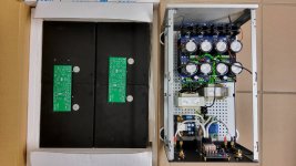
How is the perforated metal plate below the capacitor/rectifier PCB supported. I made the mistake (one time only) of connecting such a plate to a bolt going through the toroid. That is ok unless to connect anything to it, like the thermistor between signal ground and chassis. The problem is that the bolt is a 1/2 turn winding of the transformer and will develop a voltage at very high current.
new PSU and redid the layout.
That looks really nice!
Lynn, and Anand -
Thank you both for looking out for me. Truly appreciated.
The transformer is enclosed in a metal can made by Antek.

https://www.antekinc.com/ca-400-steel-cover/
The perforated plate is mounted with threaded rod and sits a cm or so above the toroid "can".
I did check more than a few times to make sure that I didn't unintentionally cut through any mask / traces this time.
I've been wanting to try some "R21" boards in my other PSUs, so killing it was the perfect excuse to take that PSU out and refit it... Yeah, that's what I had planned all along..

Thank you both for looking out for me. Truly appreciated.
The transformer is enclosed in a metal can made by Antek.
https://www.antekinc.com/ca-400-steel-cover/
The perforated plate is mounted with threaded rod and sits a cm or so above the toroid "can".
I did check more than a few times to make sure that I didn't unintentionally cut through any mask / traces this time.
I've been wanting to try some "R21" boards in my other PSUs, so killing it was the perfect excuse to take that PSU out and refit it... Yeah, that's what I had planned all along.
.Dear Hugh,This is a very serious development; congratulations!
A question: To what extent does a non-switching Class AB output stage reduce the odd order harmonics on an FFT for the entire frequency and output levels vis a vis a conventional, high feedback Class AB?
With others over a few years we have found that non-switching is a terrific idea, but in reality the odd order reductions, the 'machine tones', are small. I have done AB and A amps and found that there are subjective differences in presentation however and I wonder if we are missing something here. There might be something else the ear hears but we do not measure.......
HD
if you don't mind please look at the latest Ian's findings regarding autobias,
he proposed the solution of "almost" zero emitter resistors (several paralleled resistors/diodes),
and the circuit is nonswitching even under clipping conditions, which is unheard of before,
maybe it will be helpful to further develop the "grail":
https://www.diyaudio.com/community/...ching-auto-bias-power-amp.375141/post-7655432
regards
Pawel
Lynn, I have a few pre-assembly questions:
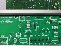
- The PCB is V1.0 20240227, the trace-correction is up to me it obviously seems? (Due to my strange reply to the poll I suppose…)
- the basic build will work out fine regardless what batch of output-devices I received? (Or should I go with the plugin-sockets and finetune it? I am not „very experienced“, see me and ZM‘s dialogues)
- these are my FETs, any advice on best pairing them?
Many thanks!
Attachments
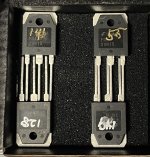
If you received "bonus" FETs, they are marked with an "X" on the backside. The four FETs without an "X" on the backside are the ones to use. Either NFET can be paired with either PFET.Lynn, I have a few pre-assembly questions:
- The PCB is V1.0 20240227, the trace-correction is up to me it obviously seems? (Due to my strange reply to the poll I suppose…)
- the basic build will work out fine regardless what batch of output-devices I received? (Or should I go with the plugin-sockets and finetune it? I am not „very experienced“, see me and ZM‘s dialogues)
- these are my FETs, any advice on best pairing them?
Many thanks!
The P1 and P2 adjustment pots should take care of differences between the FETs pairings that I have distributed.
You should not need to use sockets for the FETs unless you plan to experiment with different FETs.


I recently completed another ZD25-Mini build in a different chassis, but using the same Heatsink USA 10.08" x 7" heatsinks, and using a pair of MeanWell LRS-200N2-24 SMPS. Those power supplies are very quiet and capable of 400W power bursts. I will provide measurement details in following posts.

Here is a layout for the diyAudio Store Delux 4U chassis, with both SMPS on the bottom: (This 3D model was just an approximation to the actual Store chassis, but the overall dimensions should be correct).

Here is a layout for the diyAudio Store Delux 4U chassis, with both SMPS on the bottom: (This 3D model was just an approximation to the actual Store chassis, but the overall dimensions should be correct).
- Home
- Amplifiers
- Pass Labs
- The Holy Grail Follower Output Stage