How long do you reccon it would take to make a lets say... 20watt class AB amplifier?? ") any one want a race?? Also, it has to make noise.... it doesn't matter WHERE the noise comes from, it could be from the speaker, or from a capacitor exploring, somthing catching on fire, or even you getting electrocuted.. lol Hmmm... I think I'll do that sometime... lol... HEY SOMEONE STOLE MY SHIRT!!!!
any one want a race?? Also, it has to make noise.... it doesn't matter WHERE the noise comes from, it could be from the speaker, or from a capacitor exploring, somthing catching on fire, or even you getting electrocuted.. lol Hmmm... I think I'll do that sometime... lol... HEY SOMEONE STOLE MY SHIRT!!!!
any one want a race?? Also, it has to make noise.... it doesn't matter WHERE the noise comes from, it could be from the speaker, or from a capacitor exploring, somthing catching on fire, or even you getting electrocuted.. lol Hmmm... I think I'll do that sometime... lol... HEY SOMEONE STOLE MY SHIRT!!!! Re: Re: Cookie Power Supplies
Well: just a fun try-out.
halojoy said:
You have a strange Loudspeaker experiment.
The driver has a sort of big white papercone around it.
It is real UGLY!
Well: just a fun try-out.
Netlist said:Doesn't matter!! As long as it works ands its ugly we gladly like to see it.
Well then, here goes...
Project was a portable 100WRMS stereo amp, built around some parts I'd cobbled from a few fried stereo receivers. The portability is needed because I attend a lot of get-togethers and my portable speakers are often called on to help give a bit of tune to the proceedings. Seems only natural to want an amp with matching portability.
The proof-of-concept test circuit:
It worked amazingly well. So, I started rooting through my heatsink collection...
Nope, too big...
Ah, that's more like it!
Time to cook up a board...
... and make sure it works...
... and then stuff it with parts and mount it to the heatsink.
A TDA7293 plays peek-a-boo:
Not sure if it needs more filter capacitance yet (it only has 26,600uF per rail right now) but if I deem it as in need I'm prepared for that contingency:
And that's where I am now with it. I've got the frame partially fabbed (MIG-welded 1/2" square steel tubing) and once I finish that Iplan to wrap it with aluminum treadplate panels and a smoked-acrylic top.
It'll be a bad mofo for a little portable amp...
oO
Netlist said:Did you say "portable"?
/Hugo
Well, it -will- be... It'll be 8" wide, 7" tall, and 14" long. Weight will be about 25-30 lbs. I think.
oO
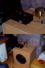
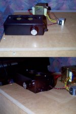
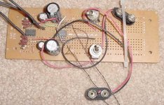
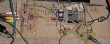
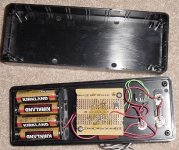
A few more pictures of my "Ugly lookin' amp" and the subwoofer that I may or may not drive with it... lol
The volume control is backwards (lol) and the fans blow air into the case, should they perhaps suck it out? lol As you can see, the powersupply is external.. LOL and there are a few too many holes in the case LOL... Total cost was nothing.... I already had all the parts that I bought for other projects, or that were recycled..
The volume control is backwards (lol) and the fans blow air into the case, should they perhaps suck it out? lol As you can see, the powersupply is external.. LOL
and there are a few too many holes in the case LOL... Total cost was nothing.... I already had all the parts that I bought for other projects, or that were recycled.. Attachments
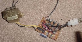
Hanzwillem said:did you really put the fans in series? not parrallel?
either way...this is good audiophile construcion
Series.... cos I am using +-24volt rails
This is bad audiophile construction.. :S lol
Plywood - Great!
Easy to cut with a normal saw, and good price.
/halo - takes whatever around, when setting up a circuit
Plywood make nice "open air chassis".paulb said:ESP3A on plywood. Rod's board, ApexJr damaged transformer, mostly surplus parts. I plan to put it in an enclosure sometime, probably with a toroid transformer and preamp.
Easy to cut with a normal saw, and good price.
/halo - takes whatever around, when setting up a circuit
Re: Plywood - Great!
/paul - who is basically lazy
Actually, it does. Great for prototypes.halojoy said:
Plywood make nice "open air chassis".
Easy to cut with a normal saw, and good price.
/paul - who is basically lazy
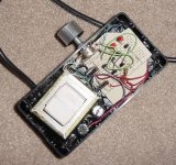
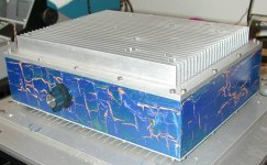
Here's my ugly amp, built into a box I picked up at a local scrap yard. The box is from a cellular phone base station diversity antenna amplifier (I think). It is 13" x 5" x 10". The walls and the base of the heat sink are 1/4" thick. The fins are about 1" high by 11.5" long.
I was able to use some of the existing holes in the box to mount the line cord socket, the fuse holder, and the input jacks. I filled the remaining holes with bondo, then drilled a few holes of my own for the power switch, volume control, and output jacks.
The nice thing about this box, besides the good size, massive amount of heatsinking, and ultra low price ($15) is that the walls are a separate piece from the top and bottom covers. To build the amp, I mounted everything on the heatsink (top cover), wired it up, tested it, then simply wired the connectors that were mounted on the walls.
I made two versions of the amp, one on perf board and one with the parts just flying all over the place. I don't like either and will replace them with a PCB, possibly a four channel one. I used a single point ground for the entire amp, and I mean EVERY ground connection goes to that point. There is no hum or noise of any detectable amount coming from either channel. I used the non inverting schematic on the front page of the LM3886 data sheet and added a parallel R and L to the output to prevent oscillation with capacitive loads (such as my electrostatic speakers). It works great! DC offset is about 600 uV in one channel and about 1 mV in the other. I did not use any blocking caps at the input.
I used a 320 VA, dual 18V power transformer that I picked up at Tanner Electronics for $25. I would have used a higher voltage for more power but this is what was available. Note- I chose the path of heresy (convention?) and used 54,000 uF per side of the power supply. The ICs are bypassed at the leads with 470 uF electrolytics and 220nF ceramic caps. It's strange , but I don't have any "weakness" in the bass.
The walls are finished with primer, followed by a base coat of tangerine orange acrylic paint, followed by a coating of crackle medium, followed by a coat of metallic blue acrylic, and finally acrylic clear coat. This was practice for an antique horn speaker that I intend to refinish to match my 1927 Neutrowound Super 6 radio.
I made a shaft extension for the volume pot out of a piece of 1/4" OD brass tubing from Lowes and a short piece of urethane air hose, slit and tie wrapped to the two shafts. It has just enough give to prevent side loading the shaft of the pot which would decrease its life considerably. It also gives a nice soft feel to the detented rotation. It absolutely does not slip. I used an ugly knob I had laying around, but I will look for a little nicer one when I get the chance.
I used politically incorrect sticky rubber feet on the bottom of the box, and equally non PC, non gold-plated bananna jacks for the speaker connections.
I was able to use some of the existing holes in the box to mount the line cord socket, the fuse holder, and the input jacks. I filled the remaining holes with bondo, then drilled a few holes of my own for the power switch, volume control, and output jacks.
The nice thing about this box, besides the good size, massive amount of heatsinking, and ultra low price ($15) is that the walls are a separate piece from the top and bottom covers. To build the amp, I mounted everything on the heatsink (top cover), wired it up, tested it, then simply wired the connectors that were mounted on the walls.
I made two versions of the amp, one on perf board and one with the parts just flying all over the place. I don't like either and will replace them with a PCB, possibly a four channel one. I used a single point ground for the entire amp, and I mean EVERY ground connection goes to that point. There is no hum or noise of any detectable amount coming from either channel. I used the non inverting schematic on the front page of the LM3886 data sheet and added a parallel R and L to the output to prevent oscillation with capacitive loads (such as my electrostatic speakers). It works great! DC offset is about 600 uV in one channel and about 1 mV in the other. I did not use any blocking caps at the input.
I used a 320 VA, dual 18V power transformer that I picked up at Tanner Electronics for $25. I would have used a higher voltage for more power but this is what was available. Note- I chose the path of heresy (convention?) and used 54,000 uF per side of the power supply. The ICs are bypassed at the leads with 470 uF electrolytics and 220nF ceramic caps. It's strange
, but I don't have any "weakness" in the bass. The walls are finished with primer, followed by a base coat of tangerine orange acrylic paint, followed by a coating of crackle medium, followed by a coat of metallic blue acrylic, and finally acrylic clear coat. This was practice for an antique horn speaker that I intend to refinish to match my 1927 Neutrowound Super 6 radio.
I made a shaft extension for the volume pot out of a piece of 1/4" OD brass tubing from Lowes and a short piece of urethane air hose, slit and tie wrapped to the two shafts. It has just enough give to prevent side loading the shaft of the pot which would decrease its life considerably. It also gives a nice soft feel to the detented rotation. It absolutely does not slip. I used an ugly knob I had laying around, but I will look for a little nicer one when I get the chance.
I used politically incorrect sticky rubber feet on the bottom of the box, and equally non PC, non gold-plated bananna jacks for the speaker connections.
Attachments
- Home
- Amplifiers
- Solid State
- UGLY Looking Amp! - but good working