

Headphone amps designed for PSRR
Posted 28th August 2015 at 04:38 AM by abraxalito
Updated 6th September 2015 at 10:57 PM by abraxalito
Updated 6th September 2015 at 10:57 PM by abraxalito
Since acquiring and modding my Taobao headphone amp I've been enamoured of creating a much more portable headphone solution to deliver aural nirvana but on the move. Whereas transformers are a very practical solution for a desktop amp, steel and copper is not only bulky but also jolly heavy and hence a no-no for anything pocket-sized.
How else to get the dynamics I'm seeking though? For these amps I'm toying with different solutions to getting better PSRR, particularly in the all-important bass region which tends to suffer in commercial portable amps. The OPS (output stage) is what needs most attention in any classAB amp - the signal stages can all be classA but for efficiency (and hence battery life) the output stage can't be conducting all the time.
A fully discrete output stage where the output devices are cascoded looks to be one solution but initially I'm looking for a simpler, more cost-effective solution with lower overhead on the supplies if possible. For the O2, RS chose some NJM4556 opamps because of their high output current (70mA) and paralleled the two amplifiers to reach 140mA. In terms of sheer output current, CMOS opamps seem to be the clear leaders, the trouble is they do tend to be extremely limited in terms of supply voltages. Mostly they're designed for 5.5V or less. The other disadvantage is that subjectively I've not yet found a CMOS opamp I like the sound of - to my ears they're noisy. Not in terms of measurable noise but noise modulation - signal correlated noise. They obscure the lowest-level details in a recording. I'm not sure of the reason for this but it could be their OPS having way too poor PSRR.
So then I'm wondering if I can improve the PSRR of a CMOS opamp by bootstrapping its supplies. This also has the secondary benefit that it'll potentially give it a much bigger output swing capability, solving the issue of its low supply voltage. It turns out that AD8532 (a 250mA capable chip) is available very cheaply here so I began with this part and fed its rails from a couple of EFs. Instead of the (more traditional) way of bootstrapping from the output, I have decided to bootstrap by feedforward - another CMOS opamp buffers the input and feeds this to the level shifters and hence to the EFs. The reason for doing this is because I want to experiment with 100% bootstrapping to maximize the PSRR - the designs I've seen in appnotes (ADI has a very good one) are not designed primarily for improving PSRR, rather output swing and content themselves with substantially less than 100% bootstrapping. With 100% bbotstrapping there would seem to be a strong potential for instability with feedback, hence my choice of feedforward.
I've added a picture showing two prototype bootstrapped amps, using different core buffers. On the right, with chips hidden behind electrolytics is the AD8532 variant; on the left is one using AD815s. Both chips are duals hence there are sharing resistors between the two halves to balance the load. I suspect the EFs (currently BC807/817) will overheat long before either chip reaches its maximum output current so adding some overload protection is a little overdue. TL431s are providing level shifting duties (in TO92 packages).
Further picture added now - the 'reference' amp which these classAB amps are aiming at in terms of SQ. An SE classA buffer where the EF is acting as the shunt element so as to render the total current draw constant. I'm using a pair of Zetex FZT688 per channel, these being the transistors with the highest beta I've been able to find (typically 1k @ 100mA Ic). They're biassed around 65mA and the supply is +/-3V - i.e. total quiescent dissipation 400mW per channel.
Update - quick cellphone shot of the 3rd generation prototype added - discrete OPS (diamond buffer as before) but bootstrapping of the output pair provided by AD8532s. This circuit I was originally running without any global feedback - i.e. the diamond buffer wasn't enclosed in an opamp's feedback loop. This worked fine until I realised that its gain then is dependent on the load impedance - only once enclosed in a fb loop would it have low enough Zout to have invariant gain with loading. Meaning the amount of bootstrap to apply to the output devices has to vary with load and hence the feedforward circuit would either need to know the load impedance or provide inaccurate bootstrapping. So now I've included a couple of MC34080s and working on getting them stable....
With the MC34080s stable (a couple of RC networks in the feedback) this thing's a bass Ogre! Listening to a recently acquired CD of 'Iolanthe' https://www.amazon.com/Gilbert-Sulliv...qid=1441263281 every tube train rumbling under the 1960 recording venue (presumably the Savoy in the Strand, London) is revealed in all its subterranean glory. Riveting stuff
Update2 - beginning to package the amp up. Power is coming from 3 * NiMH AA cells and its stepped up in voltage with two arrays of ICL7660 to reach around +/-6.5V in-circuit. An LC filter on each polarity attenuates the 10kHz switching noise by 50+dB.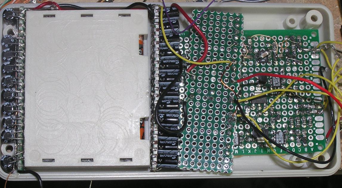
Total Comments 0


