Hello coris Which model is better than the ndk Oscillator Crystek 957.
And already on sale kit with battery per la asus ST?
Thanks
And already on sale kit with battery per la asus ST?
Thanks
Hi ciccio1112
The Crystec 957 is a very good oscillator. But I wanted to try NDK one. After I run it my board, I appreciated as a little bit better the sound quality. It may be subjective...
The battery/clock boards (last improved edition) it will come to me next week. Then the first boards it may be ready to fly away... to the customers.
The interested ones may PM me for commercial details...
This oscillator should be ndk NZ2520SD, right?
BUT then you can enter nell'Asus ST, there is contraindication thought you could only enter TCXO.
I thought you could only enter TCXO
BUT then you can enter nell'Asus ST, there is contraindication thought you could only enter TCXO.
I thought you could only enter TCXO
The oscillator one may use for this mod it can be any type, which it give the frequency signal in a performance parameters related to the price one accept to pay for it...
If one may think to use my mod, then it have to be 3,3v oscillators.
Crystek 957 and NDK are recommended.
If one may think to use my mod, then it have to be 3,3v oscillators.
Crystek 957 and NDK are recommended.
Hello Coris but Crystek and NDK are not TCXO and have an average of 50 PPM then low stability in function of temperature that does not create problems for us using audio devices that need a lot of frequency stability and we have seen that the card in the PC, where temperatures are highly variable?
The PPM TCXO instead have low around 1, so I made you this question.
The PPM TCXO instead have low around 1, so I made you this question.
Currently in my ST I mounted this TCXO:
http://www.jauch.de/ablage/med_00001006_1366728281_JT75-220413.pdf
Do you think that the NDK or Crystek sound better or not it's worth it
Thanks
http://www.jauch.de/ablage/med_00001006_1366728281_JT75-220413.pdf
Do you think that the NDK or Crystek sound better or not it's worth it
Thanks
When about oscillators, there is not only the stability (ppm...) important. There is phase noise, jitter, and so on, the rest of the parameters... While Crystek shows -150 dB phase noise, the Jauch Quartz , got no more than 130dB. Else all the oscillators are temperature compensated in a way, some other protections are in place to ensure a good frequency stability.
Crystek is quite known for its very high qualities. As the NDK is known for a very good SQ, even though not so high catalogue parameters as Crystek.
My recent experience can confirm (with a degree of subjectivity) that NDK it sounds a slighter better than Crystek.
But the main rule here, about Asus ST/STX, is that anything else but their stock low quality oscillators/resonators, it improve the board sound quality...
What oscillator is better than another it may be a long discussion. What one chose to replace the original ones on this sound card is however better...
BTW, when and if you will implement this mod, you will have the chance to try yourself in a very comfortable way, and compare in between different oscillators. It is enough to solder on the board different chips, and then connect one or another to compare how it sounds... Even more, as the last version of the clock board it give access to the user to the Enable pin of all the oscillators on board, it is enough to connect it all together to the sound card, and use that Enable pin to compare on the fly different chips...
Last edited:
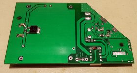
I can say that my battery powered clock board is now in its final edition, and available. It looks like in these pictures here. A 15 cm 0.8 mm coax cable for connections is included.
Some mounting recommendations and details are here bellow, for those who may want to implement it.
The best power for the charger is 7v DC. In case one may think use the 5v available in computer, I may say that this is not recommended. First because the main 5v rail is not available when the computer is off. One may think to use the stand by 5v tension (which it is available when computer off), but in this case one may know that the charger need at least 400mA to do the job. Some computer PSUs may not deliver this current on 5v Stand by rail.
Both the charger power and its GND are disconnected from any contact with the sound card/computer, when the clocks are powered and working.
For other applications of the board, there are available access to the Enable pins of all the oscillators on board. Numbered pads of Enable pins are corresponding to the number of the oscillators.
The coax provided is very delicate. Just experiment first on one end of the cable for best technique to stripe its isolation, then cut it and solder it in place. The grounding of the board to the sound card is through the coax shielding.
Attachments


I just found today a solution to a dumping mount for this clock board in its vertical position. When this board is horizontal mounted everything is more easy, but now is possible to have an elastic mount in vertical position. There is a quite big clue to avoid vibrations to a clock generating device. The computer it is really a big vibrator. To have these clocks isolated from vibrations in an enough effective way it will for sure improve the system quality.
There is about using usual silicon devices for computer fans, mounted and adapted to this task in a special way. The silicon devices give two elastic mounting/support points to the board, while the coax connection it will give the third elastic one. So, the construction it is enough stable, but not mechanical rigid. At least nobody "dance" with the computer to remove this board from its place...
The necessary parts are ordered now, and in the future this board kit it will include the dumping mounting system.
Attachments


Last edited:
I think to come here with more details about how to modify the clock system on the new edition of the Asus STX sound card. i didn`t have yet a ST version, but mainly it is the same procedure, either one may mod one or another of the two clocks on the boards.
I understood that removing the chips from the board it may be a challenge for many, and it may be quite dangerous, as the components are very small, and the traces on the boards very delicate.
Here is about to doing the mod without removing the oscillator/resonator chips from the board. The task it will be to isolate the clock input of the targeted chips from getting signal from the original components, and make possible to inject another clock signal.
The resonator on board is not using power, while the 33Mhz oscillator it will still connected to the power system, and will work further, but we will cut his connection to the chip.
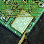
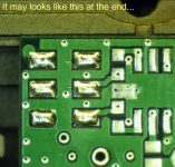
I show the pictures of the two mod areas as it are on a new board, then the commented pictures with the needed operations to succeed with this mod.
When to cut the traces, one may not insist to much in depth of the board, because it is a multilayer board design. Just scratch the traces as necessary to get rid of the copper.
It will be for sure more easy to remove some small SMD resistors/caps, and cut two traces, than remove the big clock chips.
One may be very carefully to inject the new clock signal and solder the centre of the coax cable exactly on the indicated pad, but not on some beside similar pads. It may not be fortunate to doing so...
It will come later on a tutorial about how to solder in a safe way the new oscillator chips on the battery powered board, and still heave the possibility to unsolder it again for experimenting purposes.
I think the pictures here are enough explicit, but questions are welcome.
Today I have mounted my clock board on silicon dumpers, as shown in the pictures above. My sound card it is positioned inside my computer up side down, so the clock board just hang on the silicon devices. The ideal situation I can say, which offer the best damping. It is the first time I did completely isolate this board from the mechanical vibrations of the computer. I will say that I can easily feel how the whole computer vibrate because the cooling system (which is actually very sound silent). To not talk more about other kind of vibrations which is not possible to feel it, coming from the transformers, PSU, hard discs, etc.
I can very clear say that I couldn`t believe my ears that I could actually hear the difference in sound. A very impressive sound stage, and a more precisely/detailed sound. I`m quite surprised by this experiment and the effect of a simple mechanical damping of the clock it may have a so impact, that it is possible to hear the difference in the sound quality...
I understood that removing the chips from the board it may be a challenge for many, and it may be quite dangerous, as the components are very small, and the traces on the boards very delicate.
Here is about to doing the mod without removing the oscillator/resonator chips from the board. The task it will be to isolate the clock input of the targeted chips from getting signal from the original components, and make possible to inject another clock signal.
The resonator on board is not using power, while the 33Mhz oscillator it will still connected to the power system, and will work further, but we will cut his connection to the chip.
I show the pictures of the two mod areas as it are on a new board, then the commented pictures with the needed operations to succeed with this mod.
When to cut the traces, one may not insist to much in depth of the board, because it is a multilayer board design. Just scratch the traces as necessary to get rid of the copper.
It will be for sure more easy to remove some small SMD resistors/caps, and cut two traces, than remove the big clock chips.
One may be very carefully to inject the new clock signal and solder the centre of the coax cable exactly on the indicated pad, but not on some beside similar pads. It may not be fortunate to doing so...
It will come later on a tutorial about how to solder in a safe way the new oscillator chips on the battery powered board, and still heave the possibility to unsolder it again for experimenting purposes.
I think the pictures here are enough explicit, but questions are welcome.
Today I have mounted my clock board on silicon dumpers, as shown in the pictures above. My sound card it is positioned inside my computer up side down, so the clock board just hang on the silicon devices. The ideal situation I can say, which offer the best damping. It is the first time I did completely isolate this board from the mechanical vibrations of the computer. I will say that I can easily feel how the whole computer vibrate because the cooling system (which is actually very sound silent). To not talk more about other kind of vibrations which is not possible to feel it, coming from the transformers, PSU, hard discs, etc.
I can very clear say that I couldn`t believe my ears that I could actually hear the difference in sound. A very impressive sound stage, and a more precisely/detailed sound. I`m quite surprised by this experiment and the effect of a simple mechanical damping of the clock it may have a so impact, that it is possible to hear the difference in the sound quality...
Attachments


Last edited:
Nice work as always! I think I might have to source some rubber washers to mount under my discreet clock board...
Sent from my SM-G900W8 using Tapatalk
Sent from my SM-G900W8 using Tapatalk
But keep in mind that the dampening is most efficient when the object (board) is like "floating" on the dampening mount (silicon devices). The only sustaining of the board it have to be the silicon damping system. In such case the board it may not have a very stable position, but as long as the whole main device (computer or what ever) is very stable on its position, then is no any inconvenient, and the dampening do well its job.
If one will think to have a such "construction" to listen music on a boat, then it may not be a very brilliant idea....😉😀
If one will think to have a such "construction" to listen music on a boat, then it may not be a very brilliant idea....😉😀
Last edited:
I don't like to correct people normally...but I know English isn't your first language.
The word is damping...or some might say dampening.
Dumping is what you do to a girlfriend or to the garbabge. 😉
Sent from my SM-G900W8 using Tapatalk
The word is damping...or some might say dampening.
Dumping is what you do to a girlfriend or to the garbabge. 😉
Sent from my SM-G900W8 using Tapatalk
As promised it come here some suggestions (tutorial) for a solder/unsolder technique of an oscillator (more DIY friendly)...
It may not be very right done from a specialist point of view, but I appreciate it as a good compromise in a world of experimentations as DIY is, and using means of not very high technology ones.
So, just follow please the pictures, and try to do it so...
To fully succeed in this task, one may have access to a variable power soldering iron, or two different power soldering tools. The ground pad of the board need more heat power. This is quite important in both processes (solder/unsolder).
The last pad to be soldered or unsolder it, should be the ground one.
Attachments
-
 Soldering OSC 9.jpg568.8 KB · Views: 189
 -
 Soldering OSC 8.jpg653.3 KB · Views: 191
 -
 Soldering OSC 7.jpg746.3 KB · Views: 197
 -
 Soldering OSC 6.jpg628.2 KB · Views: 176
 -
 Soldering OSC 5.jpg729.8 KB · Views: 359
 -
 Soldering OSC 4.jpg576 KB · Views: 358
 -
 Soldering OSC 3.jpg617.1 KB · Views: 374
 -
 Soldering OSC 2.jpg636.6 KB · Views: 368
 -
 Soldering OSC 1.jpg653.2 KB · Views: 397
Last edited:
Hello Coris this is my ST with a single oscillator. What are the components smd want to delete and where do I connect the central pole of the GND?
Congratulations to the explanation of the welding process.
Thank you.
Congratulations to the explanation of the welding process.
An externally hosted image should be here but it was not working when we last tested it.
Thank you.
Here are some indications to do this mod on a ST sound card...
Before connecting/soldering the coax, double check if you connect the centre of it to the pad/place which have a trace going to the processor clock input pin 46.
Using a magnifier glass is recommended.
To avoid any confusion about the coax, I may precise once more that the bride/shield of the coax is to be connected/soldered to a GND point, while its centre wire is to transport the clock signal, and should be connected as indicated.
Attachments

Last edited:
The clocks return path (the co-ax GND) must be soldered as near to the clock signal as possible, any distance will have the same effect on the clock signal integrity as a slot in a ground plane.
The nearer the better.
The nearer the better.
The clocks return path (the co-ax GND) must be soldered as near to the clock signal as possible, any distance will have the same effect on the clock signal integrity as a slot in a ground plane.
The nearer the better.
Agree. In the case of the Asus AV chip the nearest and best accessible GND point is the pin 39.
This point gnd circled in red does not go well? and very close to the clock and it would be easier to weld.
An externally hosted image should be here but it was not working when we last tested it.
- Home
- Source & Line
- PC Based
- Xonar ST/STX mods...