My friend has a Randall Satan 50 that had a completely dead clean channel. This appears to be a common problem with this amplifier and is caused by a bad LND150 in the Q2 position. I replaced the part and thought the amps was fixed, but the output is low and the signal is distorted. I think the part is damaged again.
I'm hoping I can get to the bottom of what is causing this particular MOSFET to go bad. There are two other LND150 in the amp and they don't appear to have the same problem. I replaced Q1 and it didn't make any difference. I only had 2pcs LND150, so I would like to figure out the problem before I try to source more. Please bear with my electromagical ignorance and rudimentary troubleshooting ability.
Some observations I've made for far: Q1 appears to be drawing roughly 0.5mA while Q2 is drawing 2.5mA. There is also 3.2VDC present on the gate of Q2 and only 2mV on Q1.
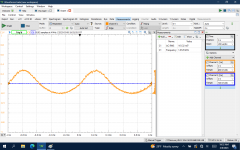
I'm attaching the full schematic, a pic of just the clean channel circuit, and a few scope shots. The signal is clean going in to Q1 and then gets messy.
I'm hoping I can get to the bottom of what is causing this particular MOSFET to go bad. There are two other LND150 in the amp and they don't appear to have the same problem. I replaced Q1 and it didn't make any difference. I only had 2pcs LND150, so I would like to figure out the problem before I try to source more. Please bear with my electromagical ignorance and rudimentary troubleshooting ability.
Some observations I've made for far: Q1 appears to be drawing roughly 0.5mA while Q2 is drawing 2.5mA. There is also 3.2VDC present on the gate of Q2 and only 2mV on Q1.
I'm attaching the full schematic, a pic of just the clean channel circuit, and a few scope shots. The signal is clean going in to Q1 and then gets messy.
Attachments


You will probably get more responses if you post this in the solid state forum. Or a site that has guitar amp forums. A simple google search for the Randall amp gets a lot of hits.
Steve
Steve
No big deal. I'll just talk to myself here.
I removed Q2 and tested it. It's bad again.
I've been trying to do as much reading and research as I can about this LND150 MOSFET. I've come to the conclusion that the 400V unregulated supply voltage is probably the culprit. I'm going to use a string of three 100V 5W zeners to regulate the voltage to 300V and go from there. I've ordered 30pcs of LND150 from Utsource. They will be here on Tuesday.
Both Q1 and Q2 have 100k resistors on their drains being supplied by 400 volts. Both gain stages are nearly identical. The LND150 is rated for a maximum of 500 volts. If the problem was high voltage then both of them would go bad.
To start I would look for bad components. Do all resistors in both stages measure the same? Are capacitors C26 and C27 defective? What happens if you disable clean gain boost?
Steve
To start I would look for bad components. Do all resistors in both stages measure the same? Are capacitors C26 and C27 defective? What happens if you disable clean gain boost?
Steve
The Q1 gate is getting DC voltage from the clean gain circuit. The Q2 gate is getting DC voltage also from its clean gain circuit. Do these operate in tandem? Or can one be enabled and the other disabled? This might account for the voltage difference.
If Q2 is drawing 2.5 ma then the power dissipation will be very close to the 0.74 watt maximum for a TO-92 package. How did you measure this? Did you measure voltage drop across the 100k drain resistor?
What is the voltage at the drain of Q1 and Q2?
Do any of the resistors in the Q2 circuit get hot to the touch?
Steve
The part is rated for 500V, but this post I came across has helped confirm my suspicion that they shouldn't be ran anywhere near that voltage...Both Q1 and Q2 have 100k resistors on their drains being supplied by 400 volts. Both gain stages are nearly identical. The LND150 is rated for a maximum of 500 volts. If the problem was high voltage then both of them would go bad.
To start I would look for bad components. Do all resistors in both stages measure the same? Are capacitors C26 and C27 defective? What happens if you disable clean gain boost?
Steve
https://www.diyaudio.com/community/...rking-properly-need-help.290388/#post-4694729
I can't test the capacitors without removing them. The problem with doing so is that I only have access to the component side of the PCB. It would take a serious amount of time and effort to remove the board, which I'm completely unwilling to do.
I know C27 isn't bad because I get a clean signal out of it. I had the gain all the way up when I took the scope screenshots. The signal on the pic labelled R44_input looks normal if I turn the gain down. It's still distorted on the output of R44 though, even with Q2 removed. I don't understand that. Maybe C25 is bad?
Yes, I had calculated the current draw by measuring the voltage across the 100k resistors. Not sure if anything is getting hot. Never worked with tube amp voltages before and it freaks me out to even stick my hand in there.
The post that you linked talks more about not using protective diodes than high voltage. Your circuit has the protective diodes discussed in that link. That was the first thing I looked for in your schematic.
The graph for the input to R46 is undistorted. The other 3 graphs are heavily distorted.
0.5 ma drop across Q1's drain resistor should put the drain at 350 volts. That is close to the value in the schematic. 2.5 ma drop across Q2's drain resistor should put the drain at 150 volts. Which is not close to the value in the schematic. And as I already mentioned that puts Q2's dissipation close to the maximum. Which would show why it fails and Q1 does not.
The two circuits are nearly identical.
A bad resistor is more likely to be the cause of the problem and I would check these first. Especially the ones in the drain or source. If resistors are undersized to dissipate the power drop through them they will eventually go bad. Measure the same resistors in each stage and provide the result.
Are the LND150s soldered or in sockets? If you can, measure the resistors without the LND150s in circuit.
How old is the amp? How much use did it get? Did something happen that seemed to trigger a failure? Is this the first time there has been a failure?
Steve
When you provided the measurements was that with the bad LND150 in circuit?
Have you replaced Q2 with a good one?
Steve
Have you replaced Q2 with a good one?
Steve
Steve, thank you very much for humoring my ignorance here. I appreciate the help.
The heavily distorted measurements were partly because I had the gain turned all the way up. If I turn the gain down, the signal out of Q1 looks fine on both sides of R44. The attached pic is of the signal in and out of Q1 with the gain at about half and the boost function off. Q2 is not installed. The original pics were with Q2 installed, but partially damaged. After I removed it I can measure around 95k from G-D and from G-S. It should have infinite resistance. This was the replacement that was good when I installed it. The original in Q2 had no output at all.
All the resistors measure within spec with the exception of R39 because of the capacitors. It goes up to 66k if I leave my meter on it for a minute, but that's the drain resistor for Q1, which is functioning properly.
I'm going to install sockets for the LND150. I don't currently have a good one to put back in Q2. I'll have them on Tuesday.
The amp isn't that old and hasn't seen much use. I think it came out in 2016? Like I mentioned before, this is a common problem with this amp model...
https://m.facebook.com/groups/1799300203651441/permalink/2695663084015144/
https://www.rig-talk.com/forum/threads/f-ck-me-randall-thrasher-50-problem.202101/
Attachments

To be sure I understand correctly what you have done. You replaced Q2 with a known 'good' LND150. And Q2 failed. If this is the case then the problem is not with Q2 but the other components. Was it instant or did it run okay for a short while?
Current draw across Q1's drain resistor provides a drain voltage close to the value in the schematic. I calculated 350 volts which is close enough.
Can you run the amp without Q2 and not damage Q1? If you can measure the voltages on Q1 before the drain resistor, at the drain and at the source.
You get the higher current draw through Q2's drain resistor if Q2 is bad or the drain, source or gate resistors are bad. In addition the clean gain boost circuit could also be the cause of the problem.
Would you post a picture of the PCB components side up?
Steve
That's not even a little "messy", for a tube guitar amp (or Silicon approximation). The signal is still stronger than the distortion. As long as you can get "less" (and later you say you can) then that is not a problem.The signal is clean going in to Q1 and then gets messy.
Wish I knew how you are blowing those FETs. Are they open in the gate, shorted in the channel, what?
@ArcticBrew Yes, I replaced the original Q2 with a known good LND150. It appeared to be working fine at first when I would switch back and forth between the overdrive and clean channels. After a couple power cycles I noticed the sound of the 1kHz test tone changed when switching channels. I made the bad assumption that Q1 was somehow the problem now and used my last good LND150 to replace it. I should have scoped it first, but I didn't.
The CH2 scope signal in my previous reply is from Q1 without Q2 installed, so Q1 appears to be working fine. The top side of Q1's drain resistor measures 378V and the bottom measures 324V (so roughly 0.5mA draw on Q1). The voltage at the source is 0.72V.
@PRR The original Q2 LND150 measures 250Ω D-S, 420k G-D/G-S with the positive meter lead on G, and 1.3k G-S/1.5k G-D with the negative lead on G. The second Q2 LND150 measures 630Ω D-S, 94.5k G-D/G-S regardless of meter lead polarity.
Attachments

I'm wondering if it could be an oscillation problem that causes it to self-destruct? I see a lot of other LND150 circuits that use much higher value gate stopper resistors. I was reading a thread on another forum where someone said they've used up to 1M without any loss in high frequency response, which makes sense. 1M in series with the 7.5pF gate capacitance yields a cut-off frequency of 21.2kHz. I don't have a wide selection of through hole resistors. I know I have 100k and 20k. I'll try a 20k gate stopper on Q2 first and see how it goes. That will lower the cut-off frequency from 21.2MHz to 1MHz. 100k would lower it to 212kHz.
One thing to keep in mind: Many of these amps have been sold and the customers are very happy with them. I have only found a couple posts about LND150 problems. If this was a design flaw in a $2,000+ amp I would expect the manufacturer to fix it because the customer feedback would be horrible. Hence we are looking for a component failure.
Oscillation is a problem that can cause a failure. The gate stopper resistor is 1k ohm. Lower values are better gate stoppers than higher values. 1k ohm is on the high side for a mosfet gate stopper but, it is a value I used in my LND150 experiments (and oscillation was not a problem). I would not increase that resistor. 100 ohms might be better but, I am not sure this is necessary.
Keep in mind that the Q1 and Q2 circuits are near identical. Q1 is not failing. We are looking for something that is different in the Q2 circuit. The only thing that I see is that may be different is the boost circuits.
Oscillation is worth exploring. And it is easy enough to assess by looking at the input and output for Q2 with an oscilloscope to see if there is a high frequency oscillation on the waveform. The scope traces you have shown appear to have a high frequency oscillation but I assumed that was an artifact of the scopes DAC. I have a PC scope that uses an 8 bit DAC. Its waveforms look similar to yours but there is no high frequency oscillation (it is a scope artifact). I also have a higher grade stand alone scope and it does not have the same artifacts. What are you using for an oscilloscope? And what is the bit depth of the DAC.
However, I think that maybe you need to ***** whether the overdrive circuit is causing problems first. You said that when you switch back and forth between overdrive and clean a few times Q2 fails. What happens if you leave it in the clean mode and don't switch it? Does it fail over time? If it doesn't then that is where we start exploring.
Steve
I have little experience with using MOSFETS, but I was under the impression that the gate stopper value is relative to the gate capacitance. Most other MOSFETs have much higher gate capacitance, so require a lower value gate stopper. For instance, the IRF820 used for the send output has a gate capacitance of 390pf while the LND150 is only 7.5pf. So the IRF820 has a gate capacitance 52x higher, yet the circuit designer chose to use a 1k gate stopper for both?
The USB scope I'm using is a 14-bit Analog Discovery 2. Some of the noise, like visible in the r46_input.jpg in my first post, was from my laptop being powered from a noisy AC inverter. The scope shot in post #9 was with the laptop running off of its battery.
The USB scope I'm using is a 14-bit Analog Discovery 2. Some of the noise, like visible in the r46_input.jpg in my first post, was from my laptop being powered from a noisy AC inverter. The scope shot in post #9 was with the laptop running off of its battery.
Wow. How do you know they are fake? Post a picture.
They may still work for you. Try them and let us know the results.
Steve
They may still work for you. Try them and let us know the results.
Steve

LOL...what a picture. I bought some a few years ago. I looked at Amazon and Ebay offerings but many of them were fake. I eventually bought 20 pieces from Mouser.
I agree do not try powering up with them in circuit.
I did as quick search online and can't find any from reputable distributors. I don't know what to tell you to do except keep searching. If you can't find anything I would be willing to give up a few of mine. But, I don't want to do that unless/until we can find a way to test the circuit and determine what is causing the burn out. Otherwise we are just throwing away more good LND150s.
Steve
I have some LND250K1 (SOT23-3 ) coming, along with adapter boards. Package power limit is less than half of the TO-92, but that shouldn't be an issue in this application since they're only biased to to 0.5mA.
- Home
- Live Sound
- Instruments and Amps
- Randall Satan/Thrasher 50 Clean Channel Problem (LND150)