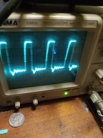
Got a kicker cxa1200, the 2045 was visually bad. Replaced it and still didn't power on. The diode d2 was out of tolerance so I replaced it and now it powers on but the drive doesn't look right. Did I cook the 2045 or is this how it's supposed to look without the power supply fets in?

Thanks
Thanks
Last edited by a moderator:
This appears to be right. What is the is the period of the waveform? Should be 50Khz
Take a screenshot of the sawtooth pin 4 of the PWM IC U3843 and post. List all DC voltages around this IC
Use Power Ground Terminal as the reference(Black probe)
Most likely the power supply mosfets have failed, In any event I recommend replacing them
Take a screenshot of the sawtooth pin 4 of the PWM IC U3843 and post. List all DC voltages around this IC
Use Power Ground Terminal as the reference(Black probe)
Most likely the power supply mosfets have failed, In any event I recommend replacing them
Pin 1. 3.8
Pim 2. 2.5
Pin 3. 0.6
Pin 4. 2.0
Pin 5. 0
Pin 6. 4.5
Pin 7. 10.74
Pin 8. 5
Power supply was on 12v
Pim 2. 2.5
Pin 3. 0.6
Pin 4. 2.0
Pin 5. 0
Pin 6. 4.5
Pin 7. 10.74
Pin 8. 5
Power supply was on 12v


When I probed the drive again that's what I got and that's what the oscilloscope was set on. And there are no power supply fets in the board. The originals blew and I was wanting to make sure everything was OK before fitting new ones. And thanks
I'm not clear what your showing me. The drive should look like the screenshot in the original post. The drive should be approximately a 20% duty cycle
which is correct in your first post.
Also, the pic with scope settings is hard to read.
The sawtooth looks as it should.
which is correct in your first post.
Also, the pic with scope settings is hard to read.
The sawtooth looks as it should.
Whenever the MOSFETs fail it usually takes out the gate driver, 2045es.
Check gate resistors (two per MOSFETs)
Check the output MOSFETs.
D2 may be a sign the DC offset turn on Transistor Q22-BC807 has failed. This will cause the amp to power up without remote.
Check gate resistors (two per MOSFETs)
Check the output MOSFETs.
D2 may be a sign the DC offset turn on Transistor Q22-BC807 has failed. This will cause the amp to power up without remote.
The screenshot in post #8 is expected in a amp running properly. You wouldn't see this with the mosfets removed.Installed the fets and they started heating up. I have a working identical cxa1200. Checked the drive and it looks like this
Remove the FETs in the non working amp and look at the drive at pin 6 UC3843, then at the gate pads of the removed FETs.
Post a pic of the PCB focusing on the Drive circuit.
Are there transistors that may be bad or is all that in the 2045?
The 2045es is an NPN & PNP in one package, so no need for additional transistors.
The amp should operate between 16 and 10 volts. Not sure what's going on here?What would cause it to only work when getting over 14volts?
It comes on with 10 volts but the drive wave doesn't build up til I get around 14. Could it be the diode I replaced is the wrong value? Thanks for the replies. I'm beyond lost here
D2 is a 1N4148 general purpose diode.
Replace D2 if necessary. Check the DC volt on either side of D2, ZD1 and around Q3. Black probe on Power GND terminal.
Recheck the DC volts on IC16 and screenshots of IC16-Pin 3 and Pin 6 and post all results and screenshots.
Post a good quality picture of the PCB. Use the pic I sent as a guide

Replace D2 if necessary. Check the DC volt on either side of D2, ZD1 and around Q3. Black probe on Power GND terminal.
Recheck the DC volts on IC16 and screenshots of IC16-Pin 3 and Pin 6 and post all results and screenshots.
Post a good quality picture of the PCB. Use the pic I sent as a guide


Okay with a 12v input D2 the voltages up top look good
Pin 3 of IC16 should be 2 volts DC. Is this screenshot when probing IC16-Pin 3? You will want to open up the Horizontal sweep/time base control.
- Home
- General Interest
- Car Audio
- CXA1200.1 drive