I'm rebuilding a pair of Kenwood L-07MII mono blocks. They were worked on previously.
One had the 2SC1586 Sanken output transistors and the other one had Onsemi MJ15024/25.
Drivers were previously replaced with 2SC4793/A1837. Slightly slower than the originals. 100MHz vs 120. Is this close enough?
I got a second set of the Onsemis to build them the same. One amp works well but one starts clicking in and out of protection as soon as I add a source. It clicks off, then after a few seconds clicks back on, then right back off again. With no source it is usually okay but it seems there can be problems there too. Issue stayed with this block when I swapped driver boards between them, ruling out the driver boards. I then did the same with the protection boards.
I lost track of which block had the Sankens in it to begin with but I swapped them back into this site and the issue went away. But I only have one set of Sankens and want the amps to match.
Back to when I was troubleshooting with the Onsemis:
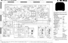
After staring at this for way too long, I noticed this amp has an extra feedback wire that going right from the amp side of the output inductor to the main feedback path to the diff pair (through a 27k resistor). So there is a feedback connection from each side of the speaker relay to the diff pair.
I tried disconnecting this and the issue went away. (But I didn't play it much like this, because I don't know how important this is and don't want any mishaps)
This wire is highlighted in the second schematic screenshot.
All electrolytics have been replaced now including the main filter caps.
I had these both fully disassembled for cleaning and couldn't find any issues or differences between them.
I'm currently testing with the dim bulb tester but it does do it plugged in directly too.
This leaves me with the following questions:
1. What's with this extra feedback wire? Is it necessary? If so, why? I can't remember seeing it in any other design.
2. Is there something about the Sankens that make them better suited for this design? And is it something I can compensate for, or do I need to track down another set? The other amp does work with the onsemis.
3. Or is something else amiss?
My understanding of design is less than the real gurus in this forum but I think I have sort of loop effect going on as this dual feedback loop creates a circle that is temporarily interrupted when the speaker relay opens. Am I on to something here?
One had the 2SC1586 Sanken output transistors and the other one had Onsemi MJ15024/25.
Drivers were previously replaced with 2SC4793/A1837. Slightly slower than the originals. 100MHz vs 120. Is this close enough?
I got a second set of the Onsemis to build them the same. One amp works well but one starts clicking in and out of protection as soon as I add a source. It clicks off, then after a few seconds clicks back on, then right back off again. With no source it is usually okay but it seems there can be problems there too. Issue stayed with this block when I swapped driver boards between them, ruling out the driver boards. I then did the same with the protection boards.
I lost track of which block had the Sankens in it to begin with but I swapped them back into this site and the issue went away. But I only have one set of Sankens and want the amps to match.
Back to when I was troubleshooting with the Onsemis:
After staring at this for way too long, I noticed this amp has an extra feedback wire that going right from the amp side of the output inductor to the main feedback path to the diff pair (through a 27k resistor). So there is a feedback connection from each side of the speaker relay to the diff pair.
I tried disconnecting this and the issue went away. (But I didn't play it much like this, because I don't know how important this is and don't want any mishaps)
This wire is highlighted in the second schematic screenshot.
All electrolytics have been replaced now including the main filter caps.
I had these both fully disassembled for cleaning and couldn't find any issues or differences between them.
I'm currently testing with the dim bulb tester but it does do it plugged in directly too.
This leaves me with the following questions:
1. What's with this extra feedback wire? Is it necessary? If so, why? I can't remember seeing it in any other design.
2. Is there something about the Sankens that make them better suited for this design? And is it something I can compensate for, or do I need to track down another set? The other amp does work with the onsemis.
3. Or is something else amiss?
My understanding of design is less than the real gurus in this forum but I think I have sort of loop effect going on as this dual feedback loop creates a circle that is temporarily interrupted when the speaker relay opens. Am I on to something here?
Attachments

Last edited:
50% of feedback is taken from near the output terminals, so that loop compensates also for relais and wire losses.
The other 50% is taken before the relais, so the amp can work correctly with no dc offset while relais still open, which is needed for proper operation of the protection circuit.
The other 50% is taken before the relais, so the amp can work correctly with no dc offset while relais still open, which is needed for proper operation of the protection circuit.

Cable lenght between amplifier and speaker? Should be <1 meter with low inductance, as in the manual.
Source is dc offset free ?
Best measure dc offset before the relais without source, with source, with input shorted.
Seems to have special output transistors with built in "emitter ballast structures"... Others may or may not work...
..."high speed amplifier", could oscillate with wrong transistors, check with scope.
The manual lists semiconductor substitutions for all transistors except the output ones...
Cable lenght between amplifier and speaker? Should be <1 meter with low inductance, as in the manual.
And 0,01 ohms, but that should only be a requirement for risetime specifications, not for general function of the amp???
High frequency phase rotations, where noted by the Kenwood engineers, when using the wrong cable. Those rotations might bring to instability, I guess.
I have no confidence that this VAS will be stable. Might be Kenwood engineers know some special tricks.

What you can do is to probe all the voltage points to see if they are on specs.
What you can do is to probe all the voltage points to see if they are on specs.
I'm trying to figure out if even the Sankens are original outputs. The schematic shows 2SC2337/2SA1007 which have an fT of 70Mhz.
But this thread shows Sanken 2SC1116/747, and a few other pictures on google show these as well. These are also 10Mhz.
I'm looking on Mouser/Digikey to see what the fastest devices there are. There are BUV22G and compliment at 8Mhz. But $30 CND each!!
MJ15016 is 18Mhz but its compliment MJ15015 isn only 6.
The MJ15024/25 are 4Mhz.
I have 4 spare Sanken 2SC1116A but no PNP.
YesOutput r-c and relais ok ?
Yes , that topology is hard to stabilize. Special combo of lead/lag compensation plus good layout.I have no confidence that this VAS will be stable.
This topology has massive open loop gain (125db+). Usually 30db gain margin at 20K.
Running the shown EF2 will do .002-.005%thd20. Run into a EF3 = PPM !
PS - looks like this one has a non-switching OPS , as well.
OS
What does OPS stand for?
Meant to link this thread in my above post:
https://audiokarma.org/forums/index.php?threads/kenwood-l-07m-major-restoration-with-bom.1029068/
Meant to link this thread in my above post:
https://audiokarma.org/forums/index.php?threads/kenwood-l-07m-major-restoration-with-bom.1029068/
L07M-II uses 2SC2337A/2SA1007AI'm trying to figure out if even the Sankens are original outputs. The schematic shows 2SC2337/2SA1007 which have an fT of 70Mhz.
But this thread shows Sanken 2SC1116/747, and a few other pictures on google show these as well. These are also 10Mhz.
I'm looking on Mouser/Digikey to see what the fastest devices there are. There are BUV22G and compliment at 8Mhz. But $30 CND each!!
MJ15016 is 18Mhz but its compliment MJ15015 isn only 6.
The MJ15024/25 are 4Mhz.
I have 4 spare Sanken 2SC1116A but no PNP.
Yes
L07M uses 2SC1116A/2SA747A
Check here, for alternative output transistor:
Last edited:
But this thread shows Sanken 2SC1116/747
The plain 07m has 2SC1116A/747A and the manual shows a troubleshooting diagram.
Any DC offset on output ?
It clicks off, then after a few seconds clicks back on, then right back off again.
Weird, to slow to protect anything in case of rail voltage on output.
Maybe you just have a little offset that is just outside the tolerance of the protection circuit.
Offset is fine.
The second amp which still has the onsemis seems to be having a similar issue though it takes longer to start.
It seems it does doesn't like the onsemis. I guess they aren't fast enough.
The second amp which still has the onsemis seems to be having a similar issue though it takes longer to start.
It seems it does doesn't like the onsemis. I guess they aren't fast enough.
What is evidence that Onsemi isn’t fast enough? Do you have a scope showing oscillation?
I doubt the dual path for the two 27k resistors (Re26, Re27) has anything to do with the problem.
OPS = Out Put Stage, I think…
I doubt the dual path for the two 27k resistors (Re26, Re27) has anything to do with the problem.
OPS = Out Put Stage, I think…
Hard to scope it when the relay is cycling in and out. And I'm afraid of blowing something.
I'd been biasing the other block that still has onsemis and it seemed fine when I first plugged it in, then I let it settle a while. I come back and the bias current is 600mV and the thing is super hot. So I shut it down. Either it was oscillating or the bias circuit went out of wack. I could try to scope that one, I'll have to stare at it for 20min+ until it goes.
It seems to work with the Sankens but not with the Onsemis. Whether it is oscillating or not it doesn't like something about them.
I'd at one point tried drivers that were too slow and it didn't react well to that either. (I'd tried the MJ15032/33 rated at 30Mhz, originals are 120, current replacements are 100.)
I found another set of (Marantz branded) Sankens kicking around here. 2SC1115 and 2SA746. They have the same power and current ratings at the original 2SC2337/compliment. But a lower voltage rating. 80V instead of 140V. The rail voltage here is 60V so I guess these would work under normal conditions but wouldn't survive fault conditions the originals might.
I’ll back away from my assertion that the parallel 27k resistors are not a problem. I maintain that the problem isn’t resolved until the amp performs properly with both in place, but your comment in first post deserves recognition.
The closed loop gain will be about 6dB higher than it should be when Re27 is absent, so it can’t be deleted. The underlying problem has to be fixed.
Good luck.
When you disconnect Re27, the feedback ratio changes by 6dB. This migHt suggest oscillation. I highly recommend scoping for possible oscillation.I tried disconnecting this and the issue went away.
The closed loop gain will be about 6dB higher than it should be when Re27 is absent, so it can’t be deleted. The underlying problem has to be fixed.
Good luck.
Last edited:
Thanks for that explanation, that explains that. I understand basic layout. The math not so much.
I looked for the circuit descriptions and found them in the original version service manual. (attached)
The Mark II service manual said to refer to the original version manual for these descriptions. I'll read through them more carefully in the morning.
I looked for the circuit descriptions and found them in the original version service manual. (attached)
The Mark II service manual said to refer to the original version manual for these descriptions. I'll read through them more carefully in the morning.
Attachments
- Home
- Amplifiers
- Solid State
- Kenwood L-07MII stability issue and interesting feedback loop