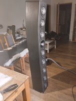
I have diy a 2,5 way 9 drivers linesource with pointsourse "function/treat"
And I have now listened to a few different filters for 1-2 months, & have started to minimize the number of components as I felt that neither a notch filter nor even using HP added anything in terms of sound.
Real happy with the sound even if maby some small tweaks is left on the xover, but use 2 different xover today for left and right speaker.
I want to finish them and mount the "finish xover" on a plate inside the speaker, so the speakers is "completely finished" to be connected from my amp.
I have a bad habbit to not finish my diy´s xover, and have loose hanging xover on the floor and parts everywhere.
And sometimes my kids ran into them, so i have to almost "start over"
So this time I WILL "finish them"!
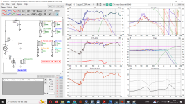
Is any of these 6 parts xover "better" purely technical, phase wise, impedance etc ?
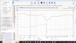
The wiggle at 1300 hz dont exist in my measurements from 2 meters or further away, and i sitt about 3,2-3,5 meters from the speakers.
Today crossed around 3K to the WG tweeter
best regards John
And I have now listened to a few different filters for 1-2 months, & have started to minimize the number of components as I felt that neither a notch filter nor even using HP added anything in terms of sound.
Real happy with the sound even if maby some small tweaks is left on the xover, but use 2 different xover today for left and right speaker.
I want to finish them and mount the "finish xover" on a plate inside the speaker, so the speakers is "completely finished" to be connected from my amp.
I have a bad habbit to not finish my diy´s xover, and have loose hanging xover on the floor and parts everywhere.
And sometimes my kids ran into them, so i have to almost "start over"
So this time I WILL "finish them"!
Is any of these 6 parts xover "better" purely technical, phase wise, impedance etc ?
The wiggle at 1300 hz dont exist in my measurements from 2 meters or further away, and i sitt about 3,2-3,5 meters from the speakers.
Today crossed around 3K to the WG tweeter
best regards John
Attachments


Will try tomorrow temp25,What would it look like in the first sim, if you increased the 1.3mH coil to about 2mH
I'm completely exhausted today after everything. 👍
A little drink helped me to "get" some more energi.What would it look like in the first sim, if you increased the 1.3mH coil to about 2mH.
It look like this 👍
Attachments

If it's 360 deg omni, or at least has equal vertical and horizontal directivity, it would be. But a narrow tall speaker are hardly ever a "point source".pointsourse
//
There is a dip and phase changes 180 degrees. What is the difference between this measurement and others?And what is that?
Phase problem ?
Why have you chosen not to set the Y positions in vituixcad?linesource
Different xovers and now more "life-like" measurement with mic in headhigh (as the final possition will be with the speakers up on the wall)There is a dip and phase changes 180 degrees. What is the difference between this measurement and others?
The 2-3 previous xovers both used big coil and notch, and have 18 components.
They where also to big to be mounted inside the speaker at the backside.
Mostly because I felt like I didn't have a grasp on what to do.Why have you chosen not to set the Y positions in vituixcad?
But now i have make my first try!
Doe´s it seems right?
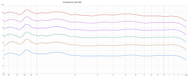
Now you can see the 2100 hz dipp more clearly.
Attachments
The phase did not suddenly change 180 degrees. The graph shifts the phase when it gets to 180, and starts it again so that it stays on the graph.
The dip is caused by three drivers fighting each other at that frequency. Personally, I would not want the outer woofers running high enough to interfere with the tweeter.
I also don't like the way the responses are shown in that software. I may be wrong, but something looks way off to me.
Why are the cones missing on half of the woofers?
Try this. Remove the tweeter from the sim for a while, and see what the woofers / mids sum looks like. It needs to be smooth. It should look like a LR4 or something. This software is not showing it, and it's showing 12dB summing which doesn't happen.
Last edited:
https://kimmosaunisto.net/Software/VituixCAD/VituixCAD_help_20.html#Driver_offsetMostly because I felt like I didn't have a grasp on what to do.
But now i have make my first try!
This is an outgrowth of another thread. It was suggested that we needed a new thread where people could post their VituixCad simulations to enhance the general knowledge of cabinet diffraction issues and baffle layout.
It started with AllenB making a point:
I added my thoughts:
It started with AllenB making a point:
Ironing a driver flat shouldn't be a problem if you choose the passband carefully, however there are many peaks and dips in measurements but many are not due to the drivers. If you EQ them all you may create problems.
I added my thoughts:
To expand on what Allen is saying: It is very enlightening to experiment with...
https://www.youtube.com/@kimmosto
Attachments
Okey.The phase did not suddenly change 180 degrees. The graph shifts the phase when it gets to 180, and starts it again so that it stays on the graph.
I was thinking "like that", but this is the first time this type of "problem" came forward for me.The dip is caused by three drivers fighting each other at that frequency. Personally, I would not want the outer woofers running high enough to interfere with the tweeter.
Been my originalplan/design to let the outer woofers fall from ca 1000 hz (and not really like it looks today)
But soundwise this also sounded "good", so i "give it a shot"
When i measured the drivers in my cabinette, i measured them in pairs.Why are the cones missing on half of the woofers?
So spl in measurement used in all my simulations are for 2 drivers, exept for the WG tweeter.
Thats why i muted one of each in every pair 1&3, 4&5 for mids and 6&7 upper woofers and 8&9 lower woffers
Attachments

You want to position the tweeter also (x,y,z) or the simulation is not worth a lot. It's only if you place all the drivers correctly on a correct box (the one you use) that it will tell you something valuable as all drivers interact with constructive or destructive interference. If you take a few out and look how the remaining ad up, it will be totally different when you add back the removed ones...
Baffle is not flat - you probably want to model this as the drivers are tilted... this only matters if you have supplied directivity data - like 15, 30, 46, 60 deg FR curves.
//
Baffle is not flat - you probably want to model this as the drivers are tilted... this only matters if you have supplied directivity data - like 15, 30, 46, 60 deg FR curves.
//
I'd put up the polar plots to see the lobing. It will only show a partial effect at this stage, but it might be enlightening.Doe´s it seems right?
Then I'd try changing the tweeter polarity.
I wrote "2,5 way 9 drivers linesource with pointsourse "function/treat""If it's 360 deg omni, or at least has equal vertical and horizontal directivity, it would be. But a narrow tall speaker are hardly ever a "point source".
And I perceive it as if the sound comes from one point & the singer's voice is exactly where it should be.
What do you want me to call it, so people understand what I'm trying to build? (and to make you happy)
I don't really know what it is. In an other thread about this speaker it was called "line source". But it is not a true line source either because such speaker has no single tweeter in the middle. I just wanted to inform you that it is not a point source, thats all. My happiness wasn't effected either way 🙂
//
//
Thanks for answering Allen!I'd put up the polar plots to see the lobing. It will only show a partial effect at this stage, but it might be enlightening.
How i make a "polar plots" ?
And can i use the measurements from 2 days ago to "make polar" ?
And i have now Y axis in Vituaxcad and X axis is "from left to right".
If my cabinette is 230 mm wide with rounded corners, and the WG is 175 mm wide placed in the middle.
What is the X axis ? (115 mm ?)
Think i did that, but will test again (when i have more energi)Then I'd try changing the tweeter polarity.
OkeyIn an other thread about this speaker it was called "line source". But it is not a true line source either because such speaker has no single tweeter in the middle. I just wanted to inform you that it is not a point source,
We maby call it an 2,5 way Array-ish/Linesource-ish with point-source-ish behavior then 🙂
"Pin-point" imaging characteristics is a hearing illusion while "point source" is a physical definition of a sound emitter - so not the same thing at all. The "point" aspect of the two may or may not coincide. Non point source speakers can produce pin-point imaging. It's hard to say what a true point source really sound like - hasn't been many done - if any.. but it is safe to say that all sounds that would come out of a PS would not necessarily sound like it came from one point.
"We" are all waiting for a true point source to emerge... 😉 that would be an event to write home about.
//
"We" are all waiting for a true point source to emerge... 😉 that would be an event to write home about.
//
- Home
- Loudspeakers
- Multi-Way
- Is any of these 2 xover technically preferable?