Yes, but F100 has 2 pair of outputs. You are not running at +/- 106v. I'm not saying it won't last for a short time but it is really stressing the SOA
Hexfet is very different from bjt. You can see that Pd, Id, Vds are far above normal requirement for most amplifiers, even Tj capability. With half load resistance, current is doubled, but this is low current design so the problem is only thermal runaway. But i have never seen an amp design that is prone to this issue. As long as Vgs is no more than 10v, it should be safe (threshold is 20v)
Jay,
So I shouldn't be that worried then? Ok, I will fire it up with 10R safety resistors anyway so that should give me some time to react in case of a problem. If I can indeed run this at 53v, the single pair might be able to push, say, 90w into 8R?
So I shouldn't be that worried then? Ok, I will fire it up with 10R safety resistors anyway so that should give me some time to react in case of a problem. If I can indeed run this at 53v, the single pair might be able to push, say, 90w into 8R?
Jay,
So I shouldn't be that worried then? Ok, I will fire it up with 10R safety resistors anyway so that should give me some time to react in case of a problem
The soa of the output stage is very predictable. You can consult the datasheet. Your circuit operation is predictable. The zupply voltage is fixed. The bias is fixed. Thermal compensation is in place and can be easily monitored to ensure it is correctly designed. The minimum load resistance can be predicted. Ensuring the speaker impedance is not below the limit is the issue as you may forget your amp capability and connect low impedance speaker. Most bjt amps, when only 1 pair cannot handle difficult load.
If I can indeed run this at 53v, the single pair might be able to push, say, 90w into 8R?
You can easily calculate that. I think yes (Even bjt is capable). Power depends on gain and bias. The hexfet is capable of that power. The supply voltage is capable (and transformer current rating). Practical limitation is gain.Whether you choose high power or low distortion.
Jay,
You make life so simple. It's like the "Staples" office supplies commercial. "Easy"!
So I have no fear or trepidation now. Will try tonight and it's gonna work!!! 😀

You make life so simple. It's like the "Staples" office supplies commercial. "Easy"!
So I have no fear or trepidation now. Will try tonight and it's gonna work!!! 😀
Last edited:
NEED HELP please.
Hallo Friends.
Now i have assembled the very nice sonal FX8 Boards
xrk gives me the tip for FH9 and i end up with this.
I started setup with 10R 10W current limiting Resistor in + - Rail, like DX Amp.
After 10 seconds the Resistor are cooking, like RickG.
Because that i have read back from page 617 #6175... to find any needed helping Information that i not blowing up the LatFet.
Prasi has used 4,7R 3-5W Resistor in each rail.
It seems nobody has any problems to get running the Amp in right bias.
At that point i think i am a dummie- where is the fault that i couldn't find?
If i start the Amp- now with 8,2R 25W the DMM shows 20V across resistor.
That means there are running ~ 2A over LatFet 😱 After 10sek i must quick switch off- they are running hot same like resistors.
Also the offset shows ~ 3,6V.
For input i have used MPSA18 hfe ~800, 2N5401/5551 and SB649/SD669
hfe ~150, years back bought from Jack Tech DIY.
Please i need advice what is wrong here.
Cheers Bangla.
Attachments

BanglaH,
Sorry to hear you are having trouble. I never had a problem like that on FX8. Usually when it hits the rail like that check that all your resistors are correct. Like you don't have a 220R when should be 22k. Next check your small signal transistors. Since you have substituted everything hard to say of it may because of that. I know pin of 2n555x is flipped vs BC546. Why use MPSA on input? Don't you have BD139/140's those are the most common drivers ?
Take a better high resolution photo of main PCB in correct vertical orientation so we can study.
Seeing how all your small signal transistors appear to match the printed orientation and you say you use 2n5551/4 (EBC) you have to flip those 180deg to CBE orientation as you have emitter and collector reversed on them. That's probably your problem.
Hallo Friends.
Now i have assembled the very nice sonal FX8 Boards
xrk gives me the tip for FH9 and i end up with this.
I started setup with 10R 10W current limiting Resistor in + - Rail, like DX Amp.
After 10 seconds the Resistor are cooking, like RickG.
Because that i have read back from page 617 #6175... to find any needed helping Information that i not blowing up the LatFet.
Prasi has used 4,7R 3-5W Resistor in each rail.
It seems nobody has any problems to get running the Amp in right bias.
At that point i think i am a dummie- where is the fault that i couldn't find?
If i start the Amp- now with 8,2R 25W the DMM shows 20V across resistor.
That means there are running ~ 2A over LatFet 😱 After 10sek i must quick switch off- they are running hot same like resistors.
Also the offset shows ~ 3,6V.
For input i have used MPSA18 hfe ~800, 2N5401/5551 and SB649/SD669
hfe ~150, years back bought from Jack Tech DIY.
Please i need advice what is wrong here.
Cheers Bangla.
There is mistake I made with tracks connecting trimpot. You can rotate trimpot 180° or turn fully clockwise then turn anticlockwise to adjust bias.
Last edited:
BanglaH,
Sorry to hear you are having trouble. I never had a problem like that on FX8. Usually when it hits the rail like that check that all your resistors are correct. Like you don't have a 220R when should be 22k. Next check your small signal transistors. Since you have substituted everything hard to say of it may because of that. I know pin of 2n555x is flipped vs BC546. Why use MPSA on input? Don't you have BD139/140's those are the most common drivers ?
Take a better high resolution photo of main PCB in correct vertical orientation so we can study.
apart from the above valid point, I also suggest BanglH to check the heat sink plate used if its touching any leads of the resistors/diodes below thus shorting the connection.

I finished casing for its AX-14, the body of 1mm metal, covered with self-adhesive, the cover has small holes for ventilation. It sounds a loud, high-quality, connected 10 ohm speaker system
Attachments


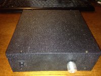


Thanks to Mile and Vargas for AX14,
sound so good, clear and tight
Nice work.
Regards
I finished casing for its AX-14, the body of 1mm metal, covered with self-adhesive, the cover has small holes for ventilation. It sounds a loud, high-quality, connected 10 ohm speaker system
Nice and compact.
Regards
Nice and compact.
Regards
My next project will be D-class, you do not have verified PCB?
Hi all audiophiles apex, i have 5 pairs of transistors FN1016 and FP1016 recover from a reciver 5.1 Aiwa AV-D58 and a 2x38 AC transformer. There is a project in which I could use this transistors and power supply?
Thanks in advance. sorry for my bad english 🙂
Regards from Romania.
Thanks in advance. sorry for my bad english 🙂
Regards from Romania.
An externally hosted image should be here but it was not working when we last tested it.
An externally hosted image should be here but it was not working when we last tested it.
My next project will be D-class, you do not have verified PCB?
Yes there is verified pcb for D200.
Yes there is verified pcb for D200.
could you please share a working PCB? Thank you 🙂
could you please share a working PCB? Thank you 🙂
Post #356 in thread: http://www.diyaudio.com/forums/class-d/182900-class-d-amp-lm566-lm393-2xirf530-36.html
Hi all audiophiles apex, i have 5 pairs of transistors FN1016 and FP1016 recover from a reciver 5.1 Aiwa AV-D58 and a 2x38 AC transformer. There is a project in which I could use this transistors and power supply?
Thanks in advance. sorry for my bad english 🙂
Regards from Romania.
You can use it for D14
Regards
- Home
- Amplifiers
- Solid State
- 100W Ultimate Fidelity Amplifier