Should I have a continuity test 'buzz' between HF + and GND.? Just doing a simple check over my XO and I'm sure this isn't right.
Maybe, there is a path via 4.7ohms. Your DMM may beep if it’s under 10ohms.
What is ohms reading?
What is ohms reading?
Last edited:
Sorry, my initial answer was wrong. Please look at edited response above. It may beep but that is normal if beep registers resistances under 10ohms. There is the 4.7ohm padding resistor. I was thinking amp input and ground. But please measure the actual ohms.
Yes its 5 ohms. I thought i made a mistake with the shunting resistor/s but maybe it is ok.?!
Thankyou for your quick response....
Thankyou for your quick response....
You are good to go. As long as not dead short. Also check amp input terminals to make sure not a dead short. Putting speaker binding posts directly on foil backed butyl sheets will cause a dead short too.
Yeah I've made that mistake with the butyl sheets before!
I'm using those little stainless steel business card things for a mounting for the speaker posts so definitely will be isolated!
Cheers X
I'm using those little stainless steel business card things for a mounting for the speaker posts so definitely will be isolated!
Cheers X
😱 .... I didn't realize yet as a filter noob who is just beginning slowly to make his homeworks : looking at the very nice Purifi and Dayton RS28 (that would sound crazy good !) that you time offset the woofers in all your schematics that have passive parts with a MiniDSP ????
i.e. : I realize than such time response optimized filters like the Harsch and else are not manageable in a single cabinet with 100% passive filters due to the extra delay of such filters ; i.e extra physical off-set -between the two drivers- that are way too big for a midwoof and a mid 🙁 !
!
First order or LR2 (as I manage 3 ways and the overlaps at the two poles of the mid could be difficult in first order) should be possible for me though... I am going to compare the HD profile due to the break-ups of the RS-225 Dayton with the SB-Acoustic SB23NBACS45-8 🙂
i.e. : I realize than such time response optimized filters like the Harsch and else are not manageable in a single cabinet with 100% passive filters due to the extra delay of such filters ; i.e extra physical off-set -between the two drivers- that are way too big for a midwoof and a mid 🙁
! First order or LR2 (as I manage 3 ways and the overlaps at the two poles of the mid could be difficult in first order) should be possible for me though... I am going to compare the HD profile due to the break-ups of the RS-225 Dayton with the SB-Acoustic SB23NBACS45-8 🙂
Last edited:


ahaha, nice center speakers jimk04. (definitly looks better fliped 90°)
rounded rebates are very beautifull
rounded rebates are very beautifull

😱 .... I didn't realize yet as a filter noob who is just beginning slowly to make his homeworks : looking at the very nice Purifi and Dayton RS28 (that would sound crazy good !) that you time offset the woofers in all your schematics that have passive parts with a MiniDSP ????
i.e. : I realize than such time response optimized filters like the Harsch and else are not manageable in a single cabinet with 100% passive filters due to the extra delay of such filters ; i.e extra physical off-set -between the two drivers- that are way too big for a midwoof and a mid 🙁
First order or LR2 (as I manage 3 ways and the overlaps at the two poles of the mid could be difficult in first order) should be possible for me though... I am going to compare the HD profile due to the break-ups of the RS-225 Dayton with the SB-Acoustic SB23NBACS45-8 🙂
I don’t use any DSP. The Harsch is achieved in Purifi TL with RS28F or RST28F in a Monacor WG300 waveguide. with a high crossover frequency and combination of waveguide offset plus upside down woofer on top offset.
The trick is use 2nd order electrical where driver falloff happens and get 4th order electro-acoustic on woofer. Cross tweeter there 2nd order and with offset, you get Harsh XO without DSP!
Hi,
I wisch I understood how you delay on a flat bafle like you are saying... it"s above my head.
Thnaks for the tip, I have to read and re read to try to understand... tomorrow is a better day, I'm quite tired right now after some hours to read about aperiodic tunning for sealed enclosures...
I wisch I understood how you delay on a flat bafle like you are saying... it"s above my head.
Thnaks for the tip, I have to read and re read to try to understand... tomorrow is a better day, I'm quite tired right now after some hours to read about aperiodic tunning for sealed enclosures...
The delay is provided by 2 things:
1. The tweeter waveguide is about 2in deep behind baffle.
2. Putting the woofer on top makes the tweeter have to travel via time of flight of a triangle hypotenuse vs direct horizontal along the woofer axis. This is good for about 3in at listening position assuming ear is at woofer height and tweeter is below woofer.
We now have circa 5in of physical delay. However, the woofer voice coil is about -2.5in behind the baffle to start with. So we have a net -2.5in delay. This is about 0.186ms of delay and this corresponds to about 5380Hz. The delay needs to be double the Harsch XO frequency. So set that about 2700Hz. So a 2700Hz 4th order low pass and second order high pass will have the proper Harsch like XO - and all done passively. A lot of this was pure luck. But I think I know the design methodology. Choose a driver with wide bandwidth so that a high XO can be used. A high crossover reduces the amount of physical setback or delay needed between the woofer and tweeter.
Last edited:

Thanks for the kind remarks.!
Plugged the sole one in last night replacing one of my re purposed Leak boxes SB17/DA25. It is a lot less efficient so it is hard to hear it over the other channel but it is definitely working as it should! I was sweating it a bit as the XO is buried in there under the dagger and it is a baffle off job to get to it. Hopefully I am happy with the padding on the HF side.
Taken a measuremt of 900mm to centre of the RS225 and that is about bang on the height of my tabs sat down...so that's good!
X in your above post you are referring to a 2700Hz Xo but aren't we at 900Hz with these?
Thank you so much X for these further inputs.
I have to take a pencil to draw that phase offset things both electrically and physically in relation to the cut off frequencies of the two poles...and the wider cut off as offseting the delay.
I am not confortable with those phases thingy...for illustration in a LR12 passband one would assume the two 180 degrees of the low pass and high pass null each other ...but I also understood that the signal has a diffetence of 360 degrees between inputt and outputt...so a complete period of delay...
Yes I need to draw it on a paper right now to try to understand...thanks again for your patience and kindness X 🙂
Hi Jim,
The comment above was in regards to the PTT6.5 TL speaker with a waveguide. It uses a Harsch XO. This speaker uses a 1st order. Just an OT reply to Diyiggy.
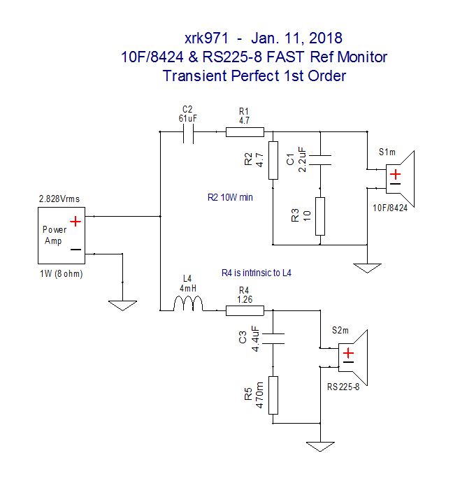
These speakers are indeed less efficient than many single fullrange speakers. If using PS95-8, sensitivity is 2dB less than ScanSpeak 10F I think.
Padding circuit probably closer to 3.3ohms/6.8ohms vs 4.7ohms/4.7ohms. But your listening preference or a measurement is best to tell.
The comment above was in regards to the PTT6.5 TL speaker with a waveguide. It uses a Harsch XO. This speaker uses a 1st order. Just an OT reply to Diyiggy.
These speakers are indeed less efficient than many single fullrange speakers. If using PS95-8, sensitivity is 2dB less than ScanSpeak 10F I think.
Padding circuit probably closer to 3.3ohms/6.8ohms vs 4.7ohms/4.7ohms. But your listening preference or a measurement is best to tell.
Thank you so much X for these further inputs.
I have to take a pencil to draw that phase offset things both electrically and physically in relation to the cut off frequencies of the two poles...and the wider cut off as offseting the delay.
I am not confortable with those phases thingy...for illustration in a LR12 passband one would assume the two 180 degrees of the low pass and high pass null each other ...but I also understood that the signal has a diffetence of 360 degrees between inputt and outputt...so a complete period of delay...
Yes I need to draw it on a paper right now to try to understand...thanks again for your patience and kindness X 🙂
You may find the technical presentation by Samuel Harsch useful as he discusses the maths behind the phase. I have a typo in my statement above, you want to delay to be 1/2 of the period corresponding to the filter frequency, or twice the frequency. So for a 2.5kHz XO frequency, the delay is equivalent to period of 5kHz full cycle.
http://petoindominique.fr/pdf/phase.pdf
- Home
- Loudspeakers
- Full Range
- 10F/8424 & RS225-8 FAST / WAW Ref Monitor