@vineethkumar01 Yes, that's the one, only the scales need to be adjusted (vertical, try 60-90dB) because its including noise. It looks like there might be some resonances at [1.5Khz, 8Khz, 10Khz, 12KHz]. Look for the peaks that decay differently (more slowly) than the adjacent freqs.
You see them in free air driver plots as well; phase plug induced. Often smoothed to look not that bad.I've always wondered how it can be that the impedance look so weird, I mean the region 400 Hz - 1 kHz. I've never seen that on any device I've been ever working with. Are those all high-Q resonances induced by the horn, or what?
(You would need a pretty long time window to capture that acoustically, BTW, if it's actually in the radiated sound.)
No, the driver itself is as clean as it can be. It has been even shown in the same graph -You see them in free air driver plots as well; phase plug induced.
There's just something obviously wrong between 0,4-1 kHz, which I would like to know what it is, as I haven't seen this in any of my data. Could it be that the whole structure was shaking during measurements?
Yes, this is something to be 3d printBut then wouldn't the adaptor need to be very very thin in the area very near to the phase plug exit so that we dont use up the space near the 25.4mm dia phase plug exit?
YesWe want to ensure that the outer surface of the new adaptor especially the part that goes inside the throat fits properly on the orange colored existing conical adaptor in above pic. So the outside of the insert that we design needs to be conical but inside will be designed as per a smooth curve.
For an axisymmetric round to round adapter Hornresp can calculate the areas and produce coordinates in a text file which can be imported as a csv and a spline made in Fusion.One more doubt I have is the following. Now I know how to make conical adaptors using fusion's morph feature. But how do we make an exponential curve like the one @docali designed. Exponential curve with Fc = 325 and T = 0.7. Is there any equation available somewhere which describes this curve. If I can make the curve in excel sheet of somewhere else probably I can rotate it in fusion to form the inner surface and then thicken it appropriately to get the outer surface also..
To make that same thing go from round to square is trickier as you need a calculator or code that can fit the area to a square or rounded square. I believe that @docali can output this from his workflow if he knows the sizes at each end. This would ideally need to be measured from the physical device and it may be better to make a test print to see what actually fits in there the best.
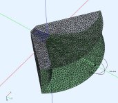
Like Don I would want to reserve judgement until a few of the more obvious potential issues have been clarified or resolved. The simulation assumes a flat wavefront from the driver, that is much more likely at the phase plug exit, at the end of a wide conical throat it will certainly not be flat anymore.
Suspiciously similar "noise" in impedance is present even in docali's own (?) data of (I guess) something similar:
https://www.diyaudio.com/community/threads/jmlc-and-yuichi-horns-measurements.395046/post-7257458
Considered as "good" and "nice", one would almost think it must be a feature rather than a manufacturing imperfection.")
But how can this originate?
https://www.diyaudio.com/community/threads/jmlc-and-yuichi-horns-measurements.395046/post-7257458
Considered as "good" and "nice", one would almost think it must be a feature rather than a manufacturing imperfection.
But how can this originate?
@DonVK
Thank you for these suggestions. We will try out the steps you mentioned next time we measure.
@WetFartz can elaborate on more details about the horn construction related aspects as I have only seen it in pictures..
For now, this is our 6ms gated on axis measurement of the horn with mic 2m away from the horn mouth
View attachment 1189049
View attachment 1189050
There are indications of some dips and peaks in the impedance magnitude response above 8kHz above which also coincides with some of the dips and peaks in frequency response. These are even in the raw driver impedance measurements as shown below.
View attachment 1189053
Even Faital pro's data sheet measurements show these but I think their magnitude response is much smoothed
View attachment 1189055
If I just apply 1/12 octave smoothing to the above captured measurement, it looks like below.
View attachment 1189057
Looks much cleaner and similar to data sheet.
From above, I am guessing that the driver break up modes could be causing some of the issues that we have been seeing. The resulting out of phase radiation from different parts of the diaphragm may be causing the kind of comb filtering sort of effects that we are seeing at high frequencies I think.
For now, @WetFartz is working on the horn trying to damp the sidewalls and the fins more. I will try to design a new adaptor based on fluid's suggestions for the ring insert.
Regarding the current adaptor, it is as you said. It is a simple lofted conic of 11.6cm length. If it would be possible for you to run some sims with the adaptor, we might get some more clues I guess. Thanks a lot for trying to help out.
[Edit]
Adding energy decay & distortion plots for the above measurement
View attachment 1189065
View attachment 1189066
First off, what has already been stated, that the driver itself is a mismatch with such a horn and the current adapter may be suboptimal.
With an acoustic loading horn there is a strong interaction between driver and horn and the measured impedance shots are not really surprising to me. Nothing to care much about the fine structure. The side peak of the driver remains an issue.
Here are two shots for the ND3N attached to LTH142 and TH4001 with brass adapter. The TH4001 was made by a well known manufacturer from solid plywood so quite well damped. CLIO pocket was used to take the shots so a well accepted manufacturer:
LTH142

TH4001

What you could try the next time is to reduce the output level (maybe about 10dB) during the impedance shots and also the fr (mic closer to horn mouth). We only need a small signal analysis just enough to be pretty well above the noise level.
I have a small android app installed on my phone called "Spectroid". This is a nice tool to discover resonances. Just have max hold activated and knock several times on your horn while the phone is recording in the nearfield. Then show us a few screenshots.
Most important: use another driver! ;-)
But you have no clue what is the origin of this phenomenon, do you?With an acoustic loading horn there is a strong interaction between driver and horn and the measured impedance shots are not really surprising to me.
It's hardly a good thing.
Last edited:
@DonVK There's POP in that space. Specifically the top and the bottom of the printed horn. I had left out the sidewalls as they looked and sounded "inert" enough. But I now plan to fill this space with POP, and also fill the fins with resin to make them solid. And with the new adaptor incoming we hope to measure this soon again.
Edit: The current adaptor is pretty solid. The printed part and the plywood are sandwiched between a layer of a mixture of sawdust and glue. There are no airgaps.
Thanks, So there is no air cavity between the PLA and plywood.
There is a simulation running with the 116mm adapter and 1.4in drive. Takes an hour or so on my machine. I'll post the results, then we can look at the other polar anomalies.
The horn output is very good in the 300-1K range so the impedance does not seem to be effecting it. Red Herring.
Edit window is over.
I should clarify, that even if the driver is mismatched (lower freq THD issues, exit angle, etc) it should still be sufficient to continue testing the horn.
How do you know? 6 ms window is not sufficient to make that conclusion.The horn output is very good in the 300-1K range so the impedance does not seem to be effecting it. Red Herring.
Thanks @docali & @DonVK
I don't think we will be able to use another compression driver at the moment. @WetFartz took great trouble in importing his current CDs at extra high price from abroad since none of the good compression drivers were available with pro audio dealers in our country at the moment. So I think we will try our best to explore the limits of performance that can achieve with his current compression driver.
Regarding the adaptor, we are trying to work on a new conical adaptor that starts right at the CD phase plug exit. Based on calculations posted above, the new length seems to be 19.6cm of which 17.6cm will be outside the horn. I don't know how to make the Exponential adaptor like what you had posted earlier. So I am trying to make a conical adaptor that transforms a circle of 2.53 cm diameter to 5.08cm sided square. Please let us know if you have suggestions for this adaptor
The only other 1.4inch CD that I have from my past experiments is an SB audience Rosso CDN 65-T (exit angle 18.36 degrees). I had used it in an LTH 142 horn and it had measured like this with the horn kept on top of my speaker (probably not supposed to be used this way).


I don't think this driver is also being much better than thr HF146 and has an added half octave of big breakup from the titanium diaphragm. However, if at all this driver is worth trying out on the current horn. I can ship it to @WetFartz for experimentation.
Regards
Vineeth
I don't think we will be able to use another compression driver at the moment. @WetFartz took great trouble in importing his current CDs at extra high price from abroad since none of the good compression drivers were available with pro audio dealers in our country at the moment. So I think we will try our best to explore the limits of performance that can achieve with his current compression driver.
Regarding the adaptor, we are trying to work on a new conical adaptor that starts right at the CD phase plug exit. Based on calculations posted above, the new length seems to be 19.6cm of which 17.6cm will be outside the horn. I don't know how to make the Exponential adaptor like what you had posted earlier. So I am trying to make a conical adaptor that transforms a circle of 2.53 cm diameter to 5.08cm sided square. Please let us know if you have suggestions for this adaptor
The only other 1.4inch CD that I have from my past experiments is an SB audience Rosso CDN 65-T (exit angle 18.36 degrees). I had used it in an LTH 142 horn and it had measured like this with the horn kept on top of my speaker (probably not supposed to be used this way).
I don't think this driver is also being much better than thr HF146 and has an added half octave of big breakup from the titanium diaphragm. However, if at all this driver is worth trying out on the current horn. I can ship it to @WetFartz for experimentation.
Regards
Vineeth
Last edited:
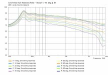
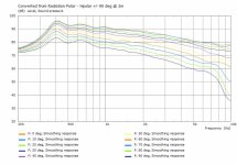
Comparing the original sim adapter (50mmx25mm) with the new adapter (36x116mm). All measurements were at 2m using constant acceleration, non normalized.
Attachments
Thanks @DonVK for the sims
It doesn't look like there is much difference between the adaptors from the simulations except below 500Hz and the overall slope down of the curves
Meanwhile the 7.5ms gated & smooothed version of the measurement looks like this from 200Hz to 10kHz

Maybe the driver is causing the differences as everyone has been poinitng out
It doesn't look like there is much difference between the adaptors from the simulations except below 500Hz and the overall slope down of the curves
Meanwhile the 7.5ms gated & smooothed version of the measurement looks like this from 200Hz to 10kHz
Maybe the driver is causing the differences as everyone has been poinitng out
If you EQ on axis flat (as per your VCAD), the polar would look good. The dip at 7Khz should be looked at because it appears in all curves angles at the same freq which suggests it might be driver related.
From the previous curves it looked like the data >10Khz was more of a problem.
From the previous curves it looked like the data >10Khz was more of a problem.
Just trying to see if 3rd party measurements of the Faital pro HF146 CD shows some of the same trends that we have seen so far. Especially the 7.5 kHz dip and the response above 10kHz.
Here are measurements from dibirama: https://www.dibirama.altervista.org...-faital-hf146-driver-2-56-8-ohm-160-wmax.html
On axis, 30 degrees and 60degrees measurements with HF146 on XT1464 horn from above link (2.83V at 1m):

Our measurements at same angles as above and shown over relatively similar scales (unknown V at 2m:

And while at it, I also traced out and made a comparison of the on-axis responses from above two plots

I think some interesting comparison's can be seen.
The 1.6kHz 2dB dip. the 7.4kHz dip, the rising response thereafter and the hash above 10k are all there..
In the meanwhile my SB audience Rosso 65 CDN-T is on its way to @WetFartz for comparison & testing
Here are measurements from dibirama: https://www.dibirama.altervista.org...-faital-hf146-driver-2-56-8-ohm-160-wmax.html
On axis, 30 degrees and 60degrees measurements with HF146 on XT1464 horn from above link (2.83V at 1m):
Our measurements at same angles as above and shown over relatively similar scales (unknown V at 2m:
And while at it, I also traced out and made a comparison of the on-axis responses from above two plots
I think some interesting comparison's can be seen.
The 1.6kHz 2dB dip. the 7.4kHz dip, the rising response thereafter and the hash above 10k are all there..
In the meanwhile my SB audience Rosso 65 CDN-T is on its way to @WetFartz for comparison & testing
Last edited:
A very helpful comparison to differentiate some of the driver related effects from the horn. Thanks @vineethkumar01 for posting those. Also very generous to lend a driver for testing. It will be very interesting to see the differences from the driver exit (18deg vs 36deg) and possible HF changes due to diaphragm material (titanium vs polymer). Matching angles would be ideal, but I've never seen sensitivity analysis to know what the tolerance is. I'm looking forward to seeing @WetFartz test measurements.
@WetFartz what XO point were you considering for the horn? Did you have a design for the LF?
@WetFartz what XO point were you considering for the horn? Did you have a design for the LF?
@DonVK: We got the inspiration for this project from @fluid's 2 way system design ideas posted around here: https://www.diyaudio.com/community/...aker-build-abec-modelling.357792/post-6883288
Hence @WetFartz has been planning to use his Faital pro 15PR400 drivers in a bass reflex box of about 120L in an alignment as shown below:


If required, we were planning to use some DSP assist, with which the response seems like below:


Here is the overall of bass response without (dot-dash blue line) and with(solid black line) DSP assist.

For crossover, we were looking to cross where the horizontal beam width of the horn matches that of the woofer. Since the horn has 90+ degrees beam width around 600-800Hz region and 15inch woofer beamwidth becomes 90 degrees around 800Hz, the intended crossover is somewhere between 600 to 800 Hz.
A 650 Hz LR4 on the horn looked like this:


Do let us know if you have any suggestions.
Hence @WetFartz has been planning to use his Faital pro 15PR400 drivers in a bass reflex box of about 120L in an alignment as shown below:
If required, we were planning to use some DSP assist, with which the response seems like below:
Here is the overall of bass response without (dot-dash blue line) and with(solid black line) DSP assist.
For crossover, we were looking to cross where the horizontal beam width of the horn matches that of the woofer. Since the horn has 90+ degrees beam width around 600-800Hz region and 15inch woofer beamwidth becomes 90 degrees around 800Hz, the intended crossover is somewhere between 600 to 800 Hz.
A 650 Hz LR4 on the horn looked like this:
Do let us know if you have any suggestions.
- Home
- Loudspeakers
- Multi-Way
- 2-way horn system based on the MK3B2